
Battery Thermal Management
Battery temperature affects charging, power output, regenerative braking, efficiency, and durability because cells cannot accept or deliver energy equally well at every temperature.
A Battery Thermal Management System (BTMS) therefore heats, cools, and equalises pack temperature according to chemistry, state of charge, required power, and the manufacturer’s control strategy.
Why Battery Temperature Matters
Battery cells are electrochemical devices. Their resistance, reaction speed, available energy, and ageing behaviour all change with temperature.
The thermal-management system must balance several priorities:
- Making sufficient power available for driving
- Allowing high charging and regenerative-braking power
- Limiting electrical losses
- Keeping cells within safe limits
- Reducing long-term degradation
- Maintaining similar temperatures across the pack
- Using as little energy as practical for heating and cooling
A battery can be within its safe temperature range without being at the best temperature for every task.
There is no single ideal battery temperature. A temperature suitable for efficient cruising may still be too low for maximum fast-charging power, while a battery prepared for high-power charging may be warmer than necessary for parking or long-term storage. Audi, for example, describes a 30–35°C preferred range for the e-tron GT battery under demanding operating and charging conditions, but this is not a universal target for every EV. (Audi)
What Happens When the Battery Is Cold
Low temperature slows ion movement through the electrolyte and electrode materials. Internal resistance increases, causing a larger voltage drop and more heat generation for a given current.
The driver may notice:
- Reduced acceleration
- Lower peak and continuous power
- Restricted regenerative braking
- Slower DC charging
- Reduced immediately available energy
- Higher consumption during short winter journeys
Cold temperature by itself does not normally damage a battery. The greater risk occurs when a cold cell is charged at high current.
In conventional lithium-ion cells with graphite-based negative electrodes, lithium ions may reach the electrode surface faster than they can be inserted into the graphite. Metallic lithium can then form on the surface through a process known as lithium plating.
Lithium plating can:
- Consume lithium that would otherwise remain available for cycling
- Increase capacity loss
- Raise internal resistance
- Form uneven deposits
- Increase safety risks in severe cases
The BMS therefore restricts charging and regenerative braking until the cells are warm enough to accept more current. Fast charging without lithium plating remains one of the key engineering challenges for cold or high-rate charging. (US Department of Energy)
What Happens When the Battery Is Hot
A warmer battery initially has lower resistance and can often deliver or accept more power. This does not mean hotter is always better.
High temperature accelerates unwanted reactions between the electrodes and electrolyte. Prolonged exposure can contribute to:
- Faster calendar ageing
- Loss of active lithium
- Growth of surface layers such as the SEI
- Electrolyte decomposition
- Gas generation
- Increased internal resistance
- Reduced cycle life
Temperature and state of charge interact. Parking a battery for a long period at both high temperature and high SOC is generally more stressful than briefly warming it before a charging session.
High temperatures during extreme fast charging are also difficult to manage. US Department of Energy research identifies battery heat generation and temperatures above roughly 45°C as important barriers to sustained extreme-fast-charging performance and battery life. The exact limit remains chemistry- and design-dependent. (US Department of Energy)
Where Battery Heat Comes From
A battery generates heat whenever current flows.
Sources include:
- Electrical resistance inside the cells
- Ion transport through the electrolyte and electrodes
- Electrochemical reactions
- Cell tabs and current collectors
- Busbars and electrical connections
- Contactors and pack junctions
- Charging and discharging inefficiency
- Heat transferred from nearby power electronics
Resistive heat increases approximately with the square of current:
Resistive heat ∝ Current² × Resistance
Doubling current can therefore generate roughly four times as much resistive heat if resistance remains unchanged.
This helps explain why demanding conditions create high thermal loads:
- High-power DC charging
- Repeated hard acceleration
- Sustained high-speed driving
- Long climbs
- Towing
- Track use
- Rapid regenerative braking
Heat is not always generated uniformly. The centre of a large cell may be warmer than its outer surface, while cells close to coolant outlets or pack edges may operate at different temperatures from cells elsewhere in the pack. NREL research has linked temperature inhomogeneity with local differences in state of charge, lithium plating, SEI growth, and degradation. (US Department of Energy)
There Is No Single Ideal Temperature
The preferred battery temperature depends on what the vehicle is preparing to do.
Normal Driving
For moderate driving, the system may prioritise low auxiliary consumption rather than heating or cooling the battery to its fast-charging target.
High-Power Driving
Repeated acceleration, towing, climbing, or high-speed driving may require additional cooling to maintain available power.
DC Fast Charging
The battery often needs to be warmer than it would during ordinary winter driving. Cell resistance must be low enough to accept high current without excessive voltage rise or lithium plating.
Parking
The car generally does not keep the battery at its fast-charging temperature while parked. Doing so would waste energy. The pack is normally allowed to move within a wider protective temperature range.
Long-Term Storage
High temperature and high SOC are undesirable for long-term storage, even though a temporarily warm battery may charge or deliver power more effectively.
Thermal management is therefore a continuous compromise between immediate performance, energy use, and ageing.
Thermal-Management System Architectures
EV manufacturers use several methods to move heat into and out of the battery.
The main approaches are:
- Passive thermal management
- Air cooling
- Indirect liquid cooling
- Direct refrigerant cooling
- Integrated coolant and heat-pump systems
Most modern EVs designed for high charging power use active liquid cooling, often connected to the vehicle’s refrigerant circuit through a heat exchanger or chiller.
Passive Thermal Management
A passively managed battery relies mainly on heat moving through:
- Cell housings
- Module structures
- The battery enclosure
- The vehicle underbody
- Surrounding air
This approach has few components and consumes little energy.
Advantages
- Low cost
- Low weight
- No pumps or coolant
- Few service points
- Low standby consumption
Limitations
- Limited ability to remove heat
- Strong dependence on ambient temperature
- Slow heating and cooling
- Difficulty maintaining uniform cell temperatures
- Poor suitability for repeated high-power charging
Passive thermal management can be sufficient for a low-power urban EV but becomes increasingly restrictive as charging speed, battery size, and sustained power increase.
Air Cooling
Air-cooled systems move ambient or cabin air through or around the battery.
The airflow may be driven by fans or by movement of the vehicle.
Advantages
- Simpler than liquid cooling
- Lower mass
- No battery-coolant circuit
- Reduced risk of coolant leakage
Limitations
- Air carries much less heat than liquid coolant
- Cooling depends heavily on air temperature
- Air ducts occupy space
- Temperature uniformity can be difficult to maintain
- Fan noise and power consumption increase under high load
An air-cooled battery may complete one fast-charging session successfully but struggle to remove enough heat for repeated charging. Nissan documented declining charging power from the second rapid-charging session onward in testing of the air-managed LEAF e+ battery. (Nissan)
Indirect Liquid Cooling
Indirect liquid cooling is the most common architecture in current high-power EVs.
A water-glycol coolant flows through:
- Cooling plates beneath the cells
- Channels beside cell rows
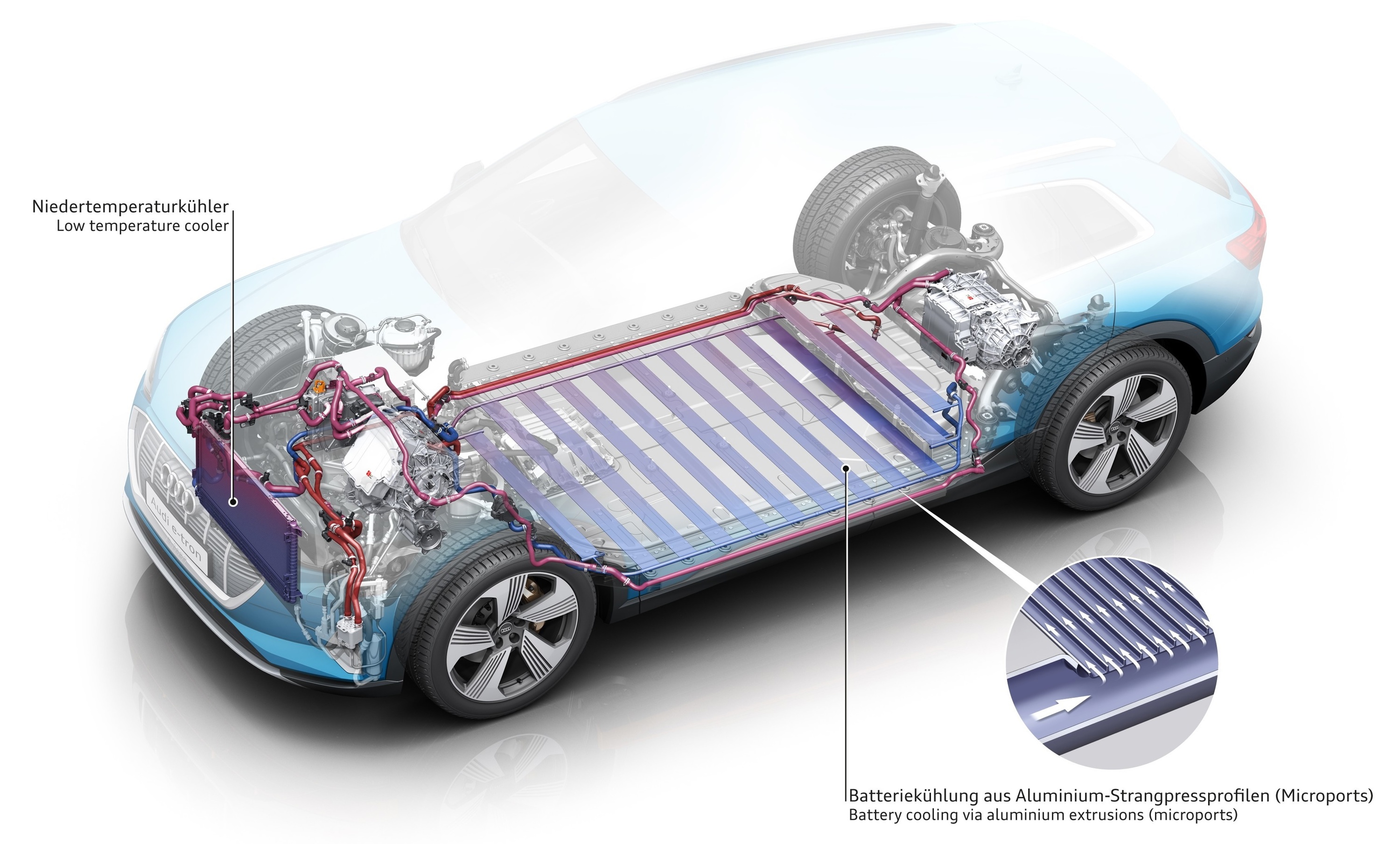
- Extruded sections inside the pack floor
- Plates contacting the broad faces of cells
- Cooling structures integrated into modules
The coolant does not normally flow inside the cells. Heat must cross several layers:
- Cell interior
- Cell enclosure
- Thermal-interface material
- Cooling plate
- Coolant
Thermal-interface material can be a pad, paste, adhesive, gel, or another conductive layer used to fill small gaps between the cell or module and cooling plate.
The Audi Q4 e-tron uses a dedicated low-temperature battery circuit with a water-glycol mixture flowing through flat channels beneath the cell compartments. Thermal paste connects the cells to the cooling structure, while a high-voltage heater warms the coolant in cold conditions. (Audi)
Advantages
- High heat-transfer capability
- Better temperature uniformity than passive or air cooling
- Effective heating and cooling through the same plates
- Suitable for high-power driving and charging
- Can be connected to a radiator, chiller, or heat pump
Trade-Offs
- Adds coolant, pumps, valves, hoses, and heat exchangers
- Increases weight and cost
- Creates possible leak and service points
- Requires careful sealing and corrosion control
- Cooling performance depends on contact between the cells and plates
Radiator Cooling
When ambient air is cool enough, the battery coolant can release heat through a radiator.
This is often the most energy-efficient cooling mode because the system may need only:
- A coolant pump
- Airflow through the radiator
- A cooling fan when vehicle speed is insufficient
Radiator cooling cannot reduce battery temperature below ambient air temperature. It can also become insufficient during hot weather or high-power charging.
Refrigerant Chiller Cooling
When the radiator cannot remove enough heat, the coolant can pass through a chiller connected to the vehicle’s air-conditioning refrigerant circuit.
The chiller transfers heat from the battery coolant to the refrigerant. The electric compressor then moves that heat through the air-conditioning system and rejects it outside the vehicle.
A simplified heat path is:
Battery cells
    ↓
Cooling plate
    ↓
Water-glycol coolant
    ↓
Refrigerant chiller
    ↓
Air-conditioning refrigerant
    ↓
Condenser and outside air
This allows the vehicle to cool the battery below ambient temperature or maintain it under sustained thermal load.
The Audi e-tron GT uses four interconnected coolant circuits. Under high drive or charging load, valves connect the battery circuit with the air-conditioning refrigerant circuit for more intensive cooling. (Audi)
Direct Refrigerant Cooling
Some designs place refrigerant channels or evaporator surfaces directly against the battery cooling structure instead of first using a separate water-glycol loop.
This can reduce the number of heat-transfer stages and provide strong cooling performance.
Trade-offs include:
- More difficult refrigerant distribution
- Greater sensitivity to pressure and sealing
- More complex service procedures
- Risk of uneven cooling if refrigerant flow is not well controlled
- Tighter integration between the battery and HVAC system
Indirect liquid cooling remains common because it separates the battery coolant circuit from the high-pressure refrigerant circuit.
Integrated Thermal Management
Modern EV thermal systems increasingly connect the battery, motors, power electronics, charging hardware, and cabin.
Depending on current conditions, heat can be:
- Removed from the battery
- Reused to warm the cabin
- Moved from the drivetrain to the battery
- Rejected through a radiator
- Moved through the refrigerant circuit
- Drawn from outside air by a heat pump
The Audi Q6 e-tron uses coolant and refrigerant heat exchangers, while its predictive control system coordinates battery heating and cooling. Nissan similarly describes an integrated system that reuses heat generated during driving and charging for the battery and cabin. (Audi)
Battery Heating Methods
Heating a cold battery requires energy. Manufacturers differ in how that energy is supplied.
High-Voltage Coolant Heater
A dedicated electric heater can warm the coolant flowing through the battery cooling plates.
Positive Temperature Coefficient, or PTC, heaters are commonly used because their electrical resistance increases as they become hotter, helping limit excessive heating.
Advantages
- Works in almost all ambient conditions
- Provides predictable heating power
- Can warm the battery without driving
- Relatively straightforward to control
Trade-Offs
- Electrical energy is converted directly into heat
- High heating power can reduce available driving range
- Adds hardware, weight, and cost
Audi uses high-voltage heaters in several EV thermal systems, including the Q4 e-tron’s coolant circuit. (Audi)
Heat-Pump Heating
A heat pump transfers heat rather than producing all of it through electrical resistance.
Possible heat sources include:
- Outside air
- Motor and inverter coolant
- Charging hardware
- Cabin exhaust air
- The refrigerant circuit
Under suitable conditions, a heat pump can move more thermal energy than the electrical energy consumed by its compressor.
Its performance falls as the temperature difference increases. Many vehicles therefore combine a heat pump with resistance heaters for rapid heating or very cold conditions.
Waste-Heat Recovery
Motors, inverters, onboard chargers, and DC-DC converters generate heat during operation.
An integrated thermal system can redirect some of this heat toward:
- The battery
- The cabin
- Another coolant loop
Waste-heat recovery is useful during driving and charging but cannot always provide enough heat after a cold start. Nissan describes reusing powertrain and charging heat as part of its integrated thermal-conditioning strategy. (Nissan)
Heat Generated During Driving
Driving itself warms the battery because current flow generates heat.
A cold pack may gradually recover charging power and regenerative braking after:
- Motorway driving
- Climbing
- Strong acceleration
- Sustained power use
This warming is not free. The heat comes from energy lost through resistance and other inefficiencies.
Some vehicles may deliberately create additional electrical load or alter drivetrain operation before charging. Whether this is used, and how aggressively, depends on the vehicle’s thermal architecture.
Cooling-Plate Placement
The position of the cooling surface influences how effectively heat can move through the cell.
Common arrangements include:
- Bottom cooling
- Side cooling
- Cooling between cell rows
- Broad-face cooling
- Tab or terminal cooling
- Double-sided cooling
Bottom Cooling
A plate beneath the modules or cells is relatively easy to integrate into a flat pack. Heat must travel from the upper parts of a tall cell down to the cooling plate.
Side or Broad-Face Cooling
Cooling the large faces of prismatic or pouch cells can shorten the heat path but requires consistent mechanical contact and compression.
Cooling Between Cell Rows
Channels between cylindrical cells provide a large contact area but take up pack space and create many repeated coolant paths.
Double-Sided Cooling
Cooling a large cell from both sides reduces the distance heat must travel and can improve temperature uniformity.
The Porsche Cayenne Electric uses cooling plates above and below each of its six modules. Porsche says the plates can both heat and cool the battery, helping the large pouch cells reach their target temperature more effectively. (Porsche Newsroom)
Temperature Uniformity
Reducing average pack temperature is not enough. The thermal system must also minimise differences between cells and within each cell.
Uneven temperature can cause:
- Different cell resistance
- Uneven current distribution
- Different states of charge
- Local ageing
- Local lithium plating
- One cell group reaching a voltage limit early
- Reduced usable capacity
Potential problem areas include:
- The centre of large cells
- Modules far from the coolant inlet
- Cells close to contactors and busbars
- Densely packed central modules
- Cells with poor cooling-plate contact
- Areas exposed to road or exhaust heat
The thermal-management system, BMS, cooling-plate design, cell format, and pack compression all contribute to temperature uniformity. DOE research into extreme-fast-charging cells identifies internal temperature gradients as a cause of uneven degradation and a limitation for large cells cooled from only one side. (US Department of Energy)
Battery Preconditioning
Battery preconditioning brings the pack closer to the temperature needed for a planned task.
The term most commonly refers to preparation for DC fast charging, but it can also include:
- Heating before departure
- Cooling before charging
- Preparing for high drive power
- Maintaining a suitable temperature while connected to AC charging
Preconditioning is not always heating. A hot battery may need active cooling before reaching a fast charger.
Fast-Charging Preconditioning
When a DC fast charger is selected in the onboard navigation system, the vehicle can estimate how much heating or cooling is needed before arrival.
Inputs may include:
- Current battery temperature
- Ambient temperature
- Distance and driving time
- Expected arrival SOC
- Recent driving load
- Expected charger capability
- Route elevation and speed
The system then adjusts heating or cooling during the journey.
Audi’s e-tron GT thermal management can intensify battery cooling roughly half an hour before arriving at a planned high-power charger, or heat the pack in cold conditions.
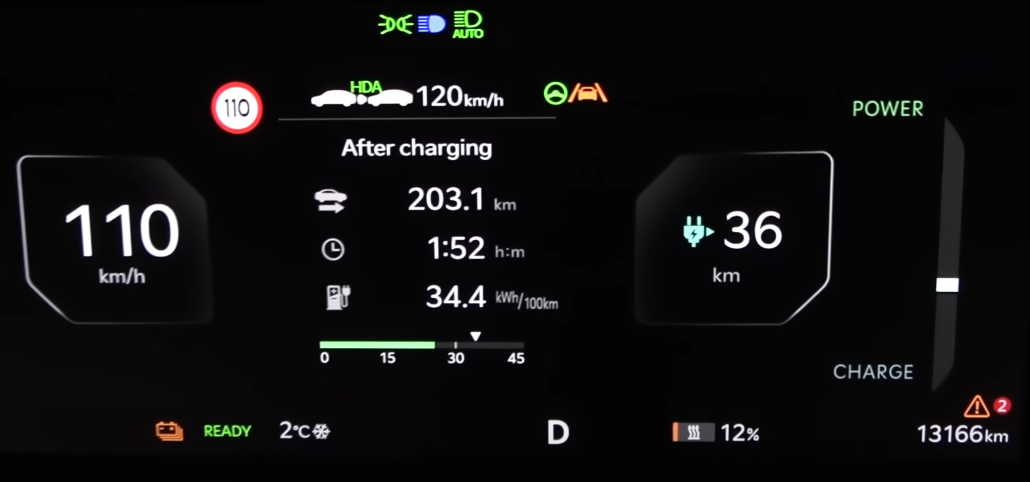
Preconditioning does not guarantee peak charging power. Charging still depends on:
- Arrival SOC
- Charger voltage and current
- Cell voltage
- Cell imbalance
- Pack temperature
- Battery condition
- The vehicle’s charging curve
- Power sharing at the charging site
Manual Preconditioning
Some EVs let the driver start battery preparation manually.
This is useful when:
- A phone or third-party route planner is being used
- The charger is missing from the onboard database
- The planned charging stop has changed
- The driver is not using route guidance
- The vehicle has selected the wrong charger type
- Charging is expected sooner than the navigation system predicts
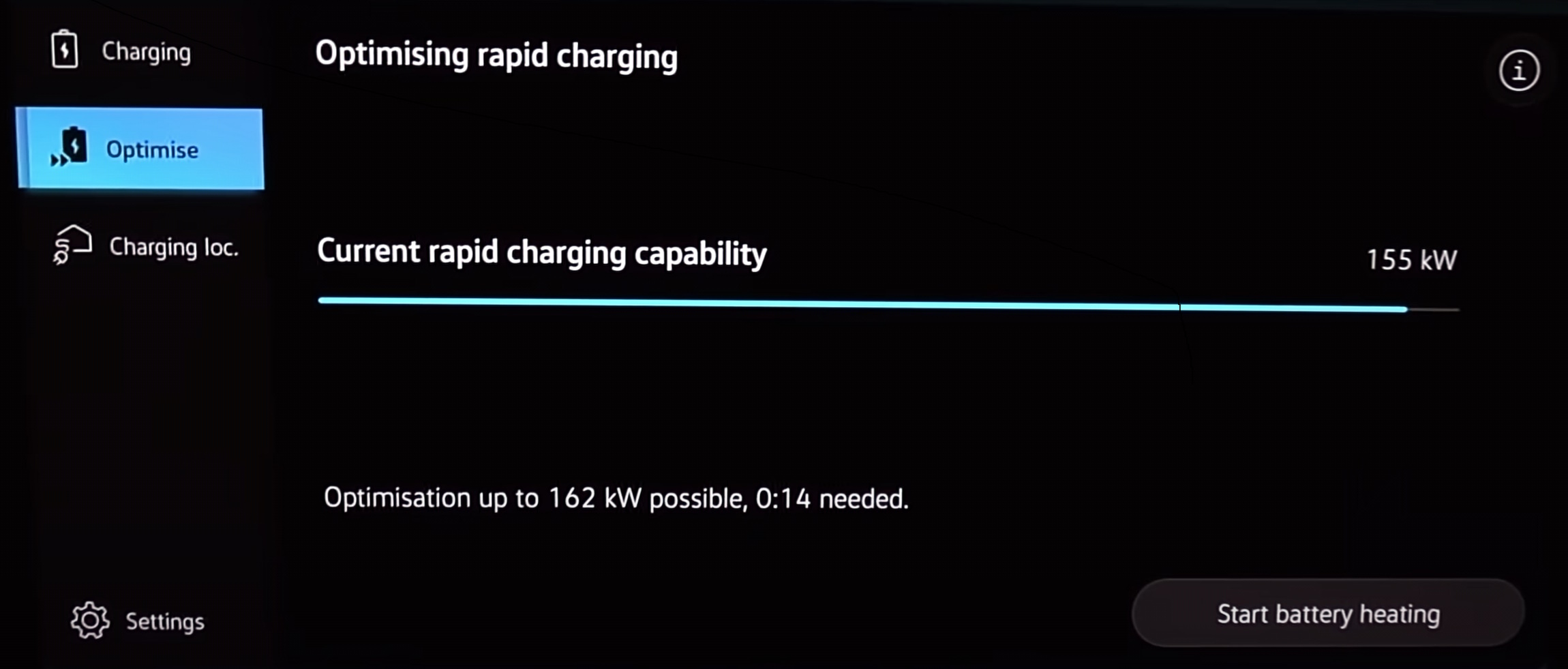
Manual preconditioning may still have restrictions:
- A minimum SOC
- Temperature-dependent availability
- A fixed maximum operating time
- Automatic shutdown
- Reduced heating power at low SOC
- Cancellation if the driver changes operating mode
Starting preconditioning also does not prove that the battery has reached its target temperature. The available preparation time and heating capacity still matter.
Preconditioning Before Departure
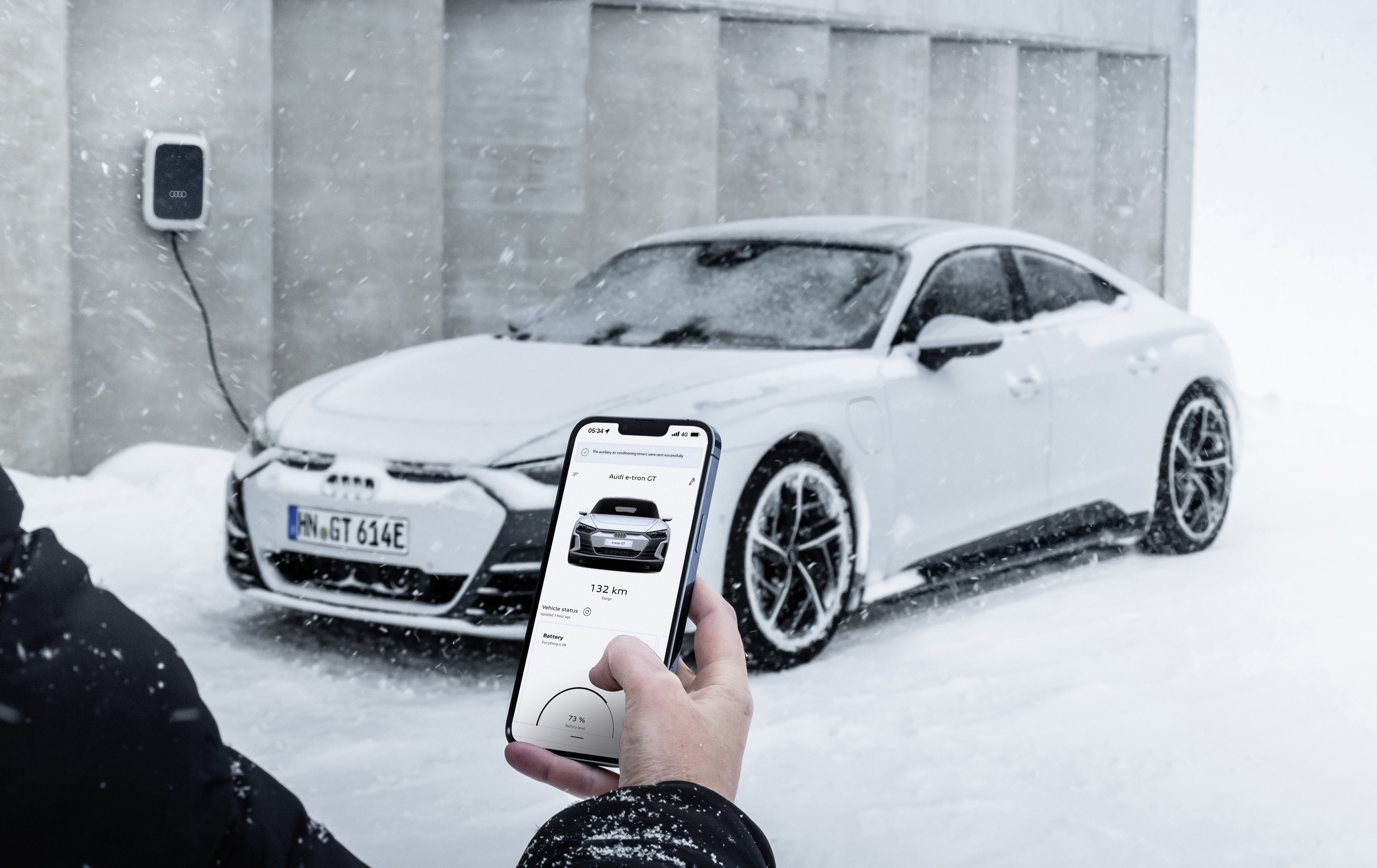
When the EV is connected to home charging, scheduled preconditioning can use grid energy to warm the cabin and, in some vehicles, the battery.
This can reduce the amount of stored battery energy used immediately after departure.
Three functions should not be confused:
- Cabin preconditioning
- Battery preconditioning
- Charging scheduled to finish near departure
Some EVs perform all three. Others heat only the cabin.
Finishing charging shortly before departure can still help because charging generates heat inside the cells. A battery that finished charging recently may start the journey warmer than one that completed charging many hours earlier.
US Department of Energy analysis notes that preconditioning while connected allows energy to come directly from the grid and can reduce cold-start energy losses during short winter trips. (US Department of Energy)
Cooling Before Fast Charging
In warm weather or after demanding use, the battery may be too hot rather than too cold.
This can occur after:
- Sustained high-speed driving
- Towing
- Mountain driving
- Track use
- A previous fast-charging session
- Parking in strong sunlight
- Repeated acceleration
The vehicle may begin active cooling well before the charging stop. A large pack has substantial thermal mass and cannot change temperature instantly.
Preconditioning therefore needs enough travel time to remove heat from the cell interiors, rather than simply cooling the measured surfaces.
Why Preconditioning May Stop at Low SOC
Battery heating and cooling consume energy.
At low SOC, the manufacturer must balance:
- Reaching the charger
- Preparing the battery
- Preserving a reserve
- Avoiding excessive cell discharge
- Maintaining cabin heating
The system may reduce or stop battery preconditioning when SOC falls below a defined threshold.
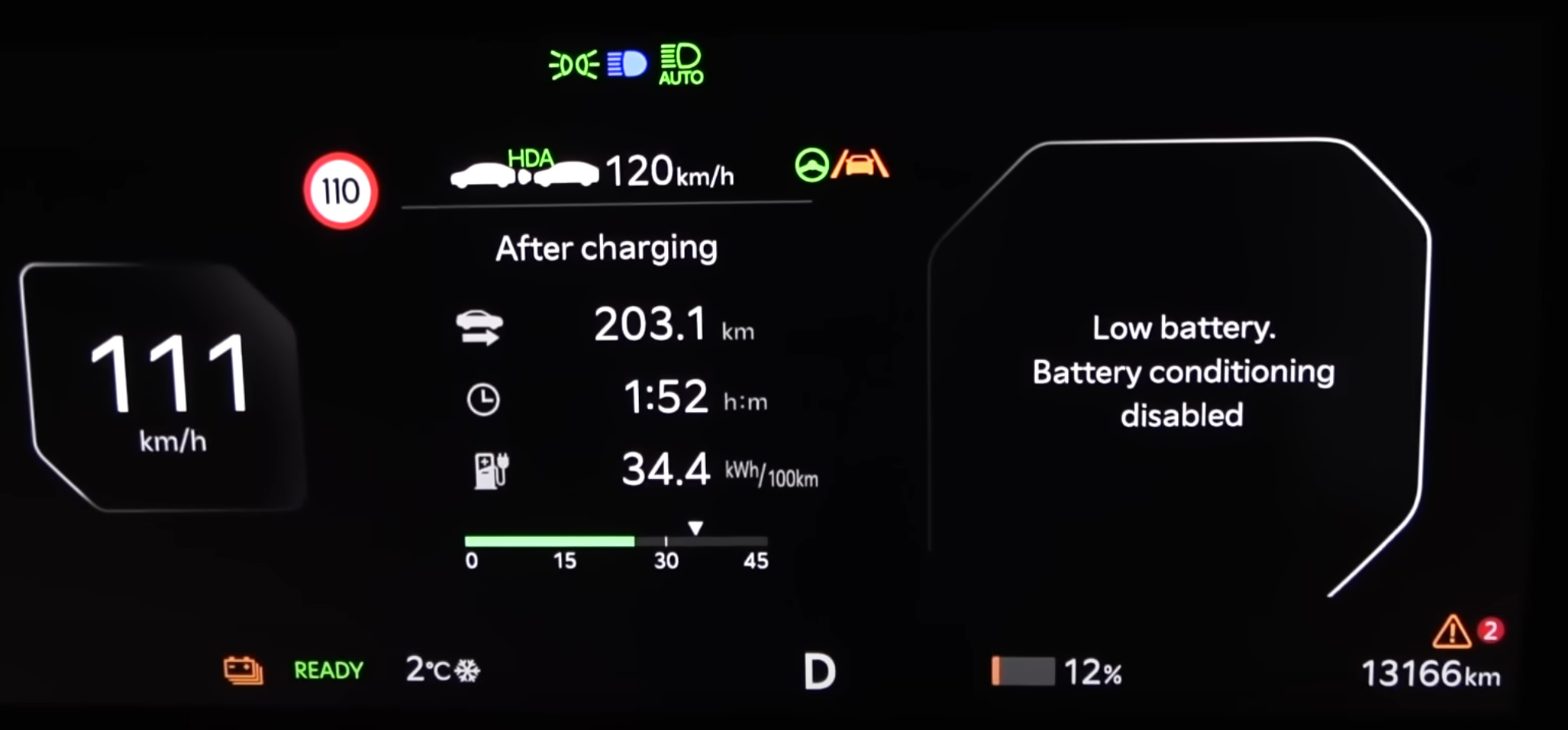
The threshold differs between vehicles and can change with software. The Kia EV9 example above shows one implementation and should not be interpreted as a general 12% rule.
Energy Use and Driving Range
Battery preconditioning uses energy. When the vehicle is unplugged, that energy comes from the traction battery and reduces the amount available for propulsion.
The main benefits are:
- Shorter charging stops
- More available drive power
- More regenerative braking
- Reduced risk of cold-charging damage
- More predictable performance
A warmer battery can have lower resistance, but this does not mean that preconditioning always increases total driving range. The energy saved through reduced losses may be smaller than the energy used for heating.
For a long journey with a fast-charging stop, spending battery energy on preconditioning can still reduce total travel time substantially.
When plugged in, grid-powered preconditioning normally provides the clearest range benefit because less stored energy is consumed before departure.
Repeated Fast Charging and Thermal Soak
Peak charging power describes only one part of road-trip performance.
After one charging session, heat remains in:
- Cell interiors
- Module structures
- Cooling plates
- Coolant
- Busbars and terminals
- The battery enclosure
This accumulated heat is often called thermal soak.
The next charging stop may begin with a warmer battery, even if the dashboard shows no warning. The thermal system must remove heat during the journey and maintain a sufficiently even temperature before charging again.
A strong long-distance system needs to:
- Prepare the battery before the first stop
- Remove heat during charging
- Continue cooling after departure
- Avoid excessive temperature rise at the next stop
- Maintain repeatable charge power
- Limit unnecessary compressor and fan consumption
The Audi e-tron GT uses interconnected coolant and refrigerant circuits to support repeated high output and fast charging. Its route-based thermal strategy can heat or cool the battery before the charging stop. (Audi)
Two EVs with the same quoted peak power can therefore perform differently over several charging sessions.
Sustained Performance
Thermal management also determines how long an EV can maintain high drive power.
A battery may support a very high output for several seconds but require lower power continuously because of:
- Cell heat generation
- Inverter or motor temperature
- Coolant temperature
- Radiator capacity
- Refrigerant-system capacity
- Ambient conditions
This matters during:
- Autobahn driving
- Towing
- Long mountain climbs
- Track driving
- Repeated acceleration
A powerful motor does not guarantee repeatable performance if the battery and thermal system cannot support it.
Thermal Management While Parked
The battery can continue heating or cooling after:
- Fast charging
- A demanding drive
- Parking in extreme heat
- Connecting to AC charging
- Completing a scheduled trip
Drivers may hear:
- Coolant pumps
- Fans
- Valves
- The air-conditioning compressor
- Electrical heaters
This can be normal even after the car is locked.
The vehicle does not normally maintain the battery at its ideal fast-charging temperature indefinitely. It instead allows a wider parked-temperature window and intervenes when required for protection, charging, or a planned departure.
Strategies vary between vehicles. Some cars actively condition the battery only while plugged in, while others may use traction-battery energy when temperatures approach protective limits.
Chemistry-Specific Thermal Behaviour
The thermal-management requirement depends partly on cell chemistry, but the complete vehicle design remains decisive.
Nickel-Rich Lithium-Ion
NMC, NCA, and NCMA cells can provide high energy density and power.
Their performance depends on careful control of:
- High temperature
- High cell voltage
- Charging current
- Cooling uniformity
- Time at high SOC
Nickel-rich cells are widely used in vehicles requiring long range and high power, but they place substantial demands on cooling and control.
Lithium Iron Phosphate
LFP offers strong thermal stability and long cycle life.
Its main thermal limitation is cold operation. Cold LFP cells can show:
- Greater charging restriction
- Reduced regenerative braking
- Lower power
- More difficult SOC estimation
- Greater dependence on active heating
A well-heated LFP battery can still provide strong winter charging performance. Chemistry alone does not determine the result.
Sodium-Ion
Some sodium-ion designs are being developed specifically for broad-temperature operation.
CATL claims that its Naxtra passenger-vehicle sodium-ion cell retains 90% usable power at −40°C. This is a manufacturer specification for that particular product, not a universal property of all sodium-ion cells. (CATL)
Sodium-ion packs still require thermal management because:
- Charging creates heat
- Cell ageing remains temperature-dependent
- Temperature uniformity matters
- Power and charging limits still change with temperature
- The passenger cabin and powertrain share thermal resources
Thermal Management and Battery Ageing
Thermal management affects both cycle ageing and calendar ageing.
A good system limits:
- Long periods at excessive temperature
- Fast charging when cells are too cold
- Large differences between cell temperatures
- Repeated high-power use without sufficient cooling
- Local hotspots
- Long-term exposure to high temperature and high SOC
The goal is not to hold the battery at one temperature at all times. That would consume too much energy.
Instead, the system uses different temperature targets for:
- Driving
- Fast charging
- Parking
- AC charging
- High power
- Battery protection
A vehicle with strong cooling may deliberately allow the cells to become warm during fast charging and then remove that heat afterward. Brief controlled warming is different from prolonged heat exposure.
Normal Cooling Is Not Thermal-Runaway Protection
Normal thermal management removes heat created during ordinary charging and driving.
Thermal runaway is a different condition. It involves self-accelerating internal reactions that can release heat faster than the standard cooling system can remove it.
If thermal runaway begins inside a cell, opening the contactors and running coolant pumps may not stop the reaction. The energy is already stored chemically inside the cell.
Protection also depends on:
- Cell chemistry
- Manufacturing quality
- Cell spacing
- Thermal barriers
- Vent direction
- Gas-management paths
- Pack pressure relief
- Fault detection
- Crash protection
- Prevention of propagation to neighbouring cells
Thermal management helps prevent cells from reaching abusive conditions during normal use, but it is not a substitute for dedicated thermal-propagation protection. NREL treats ordinary pack thermal control and thermal-abuse containment as related but separate engineering problems. (NREL)
Thermal-System Trade-Offs
A more capable thermal system is not free.
It adds:
- Weight
- Cost
- Coolant
- Pumps
- Valves
- Heat exchangers
- Refrigerant components
- Sensors
- Software complexity
- Electrical consumption
- Service and leak points
A large chiller and compressor can support repeated high-power charging but occupy more space and consume more energy.
A simpler system may be entirely appropriate for a low-cost urban EV that rarely fast charges. The same system could be inadequate in a long-range vehicle intended for repeated charging, towing, or sustained high-speed use.
Thermal-management technologies therefore involve trade-offs between performance, cost, efficiency, packaging, and durability. DOE technology roadmaps likewise identify added weight, cost, and complexity as central thermal-management constraints. (US Department of Energy)
What EV Buyers Should Compare
Manufacturers rarely publish enough technical detail to compare cooling-system hardware directly. Real-world behaviour provides better evidence.
Useful questions include:
- Does the car automatically precondition when navigating to a charger?
- Can preconditioning also be started manually?
- Does a scheduled departure warm the battery or only the cabin?
- How long does the battery need to prepare in winter?
- At what SOC does preconditioning stop?
- Can the car maintain charging speed over repeated stops?
- How does charging perform in hot weather?
- Is regenerative braking heavily restricted when cold or full?
- Does the car retain drive power during towing or sustained high speed?
- Can battery temperature be shown to the driver?
- Does the vehicle continue cooling after charging?
- Is a heat pump standard, optional, or unavailable?
Peak charging power alone says little about thermal performance. The more useful measure is whether the EV can arrive at a charger with the battery prepared, maintain a strong charging curve, and repeat that performance throughout the journey.
For related battery behaviour, see Battery Charging and Charging Performance, Battery Degradation, and EV Battery Safety and Failure Management.
Sources
- Audi e-tron GT battery and thermal management
- US Department of Energy extreme-fast-charging technology assessment
- US Department of Energy heat generation in extreme fast charging
- Nissan Technical Review 2022
- Audi Q4 e-tron battery thermal management
- Audi Q6 e-tron battery and charging
- Nissan EV thermal conditioning
- Porsche Cayenne Electric high-voltage system
- US Department of Energy cold-weather EV performance study
- CATL Naxtra battery and dual-power architecture
- NREL cell-to-pack integration study
- US Department of Energy electrochemical energy storage roadmap