
Battery Management System
An EV’s battery management system (BMS) is the electronic and software layer that keeps the traction battery within its permitted operating limits by measuring the pack, estimating conditions that cannot be sensed directly, and controlling how it connects to the vehicle. It communicates charge, regenerative-braking, and drive-power limits to the charger, inverter, and thermal-management system, which perform the energy conversion and temperature control.
What the BMS measures, estimates, and controls
A high-voltage battery may contain hundreds or thousands of physical cells. Cells connected in parallel share a terminal voltage, so the BMS normally monitors each parallel group as one voltage point. A pack described as 108s4p, for example, generally has 108 monitored series-group voltages rather than 432 independent cell-voltage measurements.
The most important direct measurements typically include:
- Voltage of every monitored cell group
- Total pack voltage and voltages at key points around the contactors
- Current entering or leaving the pack
- Temperatures at selected cells, modules, cooling plates, busbars, and electrical components
- Electrical isolation between the high-voltage system and the vehicle chassis
- High-voltage interlock, contactor, fuse, and precharge-circuit status
Pack voltage alone is not enough. Two cell groups can deviate in opposite directions while their combined voltage still looks normal. The highest-voltage group can end a charge, and the lowest-voltage group can limit discharge, even when the pack average appears acceptable.
Several of the values drivers and service tools use are not direct sensor readings. The BMS estimates them from voltage, current, temperature, time, battery models, and stored history. These estimates include:
- State of charge (SOC)
- State of energy (SOE)
- State of power (SOP)
- State of health (SOH)
- Usable capacity and internal resistance
- Maximum permitted charge and discharge current
The BMS then acts on that information. It can operate the pack contactors and balancing circuits, manage the precharge sequence, request heating or cooling, and communicate charge, discharge, and regenerative-power limits to other controllers. Automotive BMS platforms therefore combine cell monitoring, pack-level voltage and current sensing, isolation monitoring, contactor control, and high-voltage interlock functions. (Texas Instruments)
How BMS hardware is organised
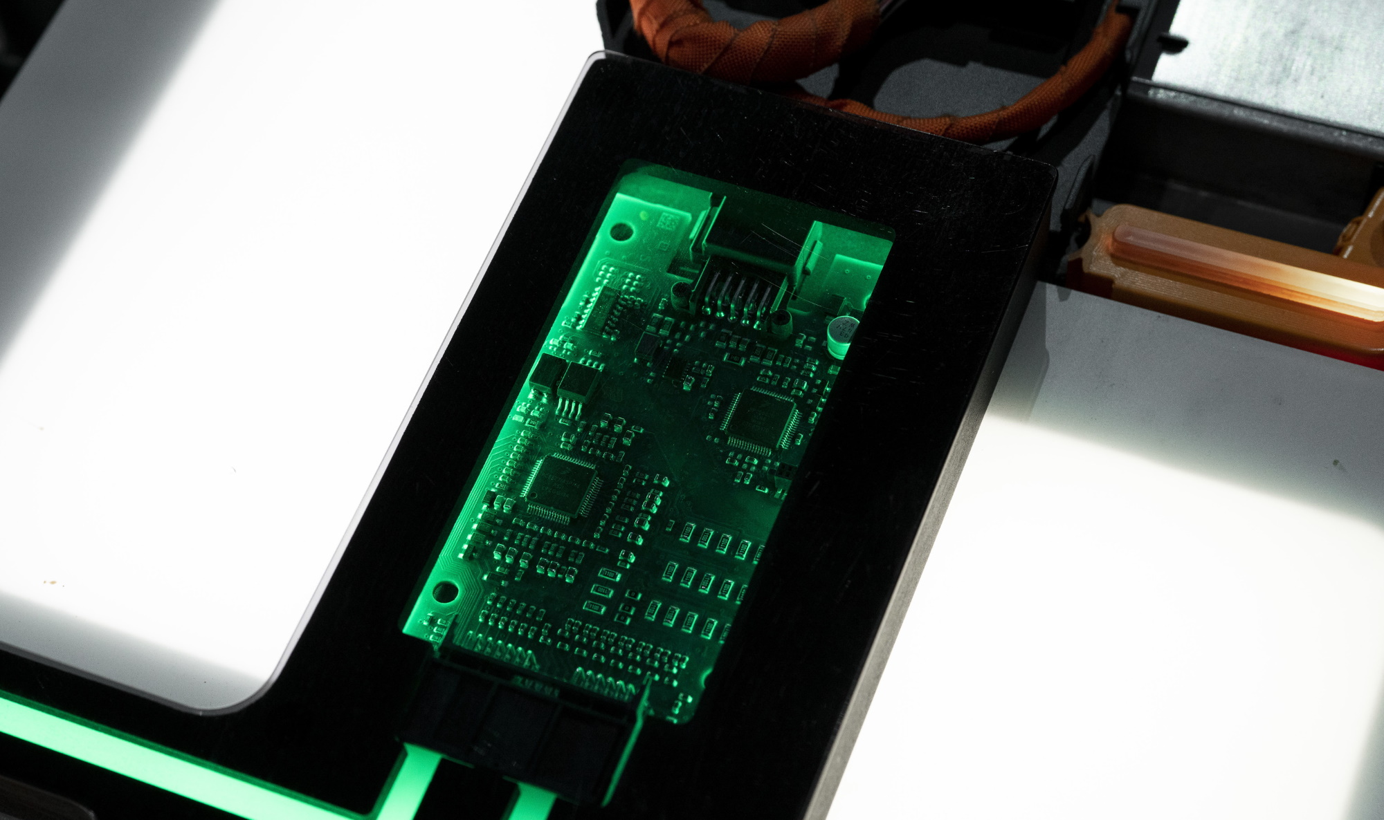
A modern BMS is distributed through the battery rather than contained on a single circuit board. Component names vary, but many systems divide the work between cell-monitoring units, a central battery controller, and a battery junction box. NXP’s 800-volt reference architecture uses the terms CMU, BMU, and BJB for these three layers. (NXP)
Cell-monitoring units
A Cell-Monitoring Unit (CMU) sits close to a group of cells or modules. Its analogue front-end circuits measure cell-group voltages and temperature-sensor inputs. They may also perform passive balancing and monitor connections or other local sensors.
Several CMUs can be linked in an isolated daisy chain, a ring, CAN FD, or another automotive communication network. Measurements must arrive reliably despite electrical noise and large voltage differences between sections of the pack.
Battery-management unit
The Battery-Management Unit (BMU) is the central controller. It collects the measurements, checks that they are plausible, runs state-estimation algorithms, calculates operating limits, stores diagnostic information, and exchanges data with the vehicle controller, charger, inverter, and thermal controller.
Battery junction box
The Battery Junction Box (BJB) carries pack-level sensing and high-current switching hardware. Depending on the design, it can contain:
- Main positive and negative contactors
- A precharge contactor and resistor
- Pack-current and high-voltage sensors
- The main fuse and, where fitted, a pyrotechnic disconnect
- Isolation-monitoring hardware
- High-voltage connections to the inverter, charging system, and other loads
Comparing voltages on the battery and vehicle sides of the contactors lets the controller verify whether the commanded switching actually happened. Current and voltage measurements also need accurate timing because they are used together for power, resistance, SOC, and SOH calculations. (Texas Instruments)
Wired and wireless communication
Most battery packs use wired communication between their monitoring units. Redundant or ring-based links can allow messages to take another path if one connection fails.
A wireless BMS replaces part of this internal signal harness with a purpose-built radio network. It can reduce connectors, cable routing, and assembly complexity, but it does not remove cell-monitoring electronics, voltage-sense connections, temperature sensors, balancing circuits, power supplies, diagnostics, or the need for reliable and secure communication. Wireless automotive BMS hardware links the cell-monitoring devices to the central BMS controller; it is not a wireless connection to the battery cells themselves. (Analog Devices)
Connecting the high-voltage battery
Switching off an EV does not make the cells or internal busbars voltage-free. Instead, large electrically operated switches called contactors normally disconnect the battery’s external positive and negative terminals from the rest of the vehicle.
Before closing those contactors, the BMS checks relevant cell voltages and temperatures, isolation resistance, interlock status, communication, and stored faults. It then performs precharge.
The inverter, onboard charger, DC-DC converter, and other high-voltage electronics contain capacitors. Connecting an uncharged capacitor directly to the battery would create a large inrush current that could pit or weld contactor surfaces and stress cables, connectors, and fuses. A conventional precharge circuit first connects the vehicle’s high-voltage bus through a resistor. When the bus voltage has risen close enough to pack voltage, the main contactors can close and bypass the resistor. (Texas Instruments)
A simplified startup sequence is:
- The low-voltage electrical system wakes the BMS and the other required controllers.
- The BMS checks the monitored battery and high-voltage-system conditions.
- The precharge path and the required main contactor are closed.
- The external high-voltage bus charges through the precharge resistor.
- The BMS compares pack voltage with the voltage beyond the contactors.
- When the difference is within the permitted range, the remaining main contactor closes and the precharge path opens.
The exact switching order varies by design. The purpose is always to establish the high-voltage connection without uncontrolled inrush current.
Isolation monitoring and the high-voltage interlock
The traction circuit is normally isolated from the vehicle body. An isolation monitor measures the electrical resistance between the high-voltage system and the chassis. Reduced isolation can result from damaged insulation, water or coolant intrusion, contamination, a connector problem, or a fault in the battery, inverter, motor, charger, or high-voltage cabling.
The High-Voltage Interlock Loop (HVIL) is a separate low-voltage monitoring circuit routed through selected high-voltage connectors, covers, and components. An interrupted loop tells the vehicle that part of the high-voltage system may be disconnected or open. Depending on the condition, the vehicle may stop charging, open the contactors, or prevent them from closing.
This is also why a weak 12-volt or 48-volt battery can immobilise an EV whose traction battery still contains plenty of energy. The BMS, controller electronics, and contactor coils require low-voltage power before the high-voltage battery can be connected to the vehicle.
Estimating charge, energy, power, and health
Battery percentage, remaining energy, available power, and battery health answer different questions. Treating them as one value creates much of the confusion around battery diagnostics.
State of charge
State of Charge (SOC) is the estimated charge level within the battery’s defined operating window. The percentage shown to the driver normally maps to the usable window, not the cells’ complete electrochemical range. Capacity may be reserved above displayed 100% and below displayed 0%, as explained in Battery Buffer and Usable Capacity.
SOC cannot be measured by a single sensor. The BMS combines several methods:
- Coulomb counting integrates current over time to track charge entering and leaving the battery.
- Voltage-based correction compares measured or modelled open-circuit voltage with chemistry-specific reference data.
- Battery models predict voltage response using SOC, current, temperature, resistance, recent history, and ageing-related parameters.
- Observer algorithms, including Kalman-filter variants, compare model predictions with measurements and correct the estimate.
Coulomb counting reacts immediately to energy flow, but a small current-sensor bias accumulates into a larger error over time. Voltage provides a reference, but terminal voltage also changes with load, temperature, resistance, hysteresis, and the time since charging or discharging. Production algorithms therefore combine measurements and models rather than trusting one method alone. (Analog Devices)
SOC estimation is especially demanding for LFP cells through the middle of their operating range because the open-circuit-voltage curve is comparatively flat and affected by hysteresis. A small voltage error can represent a much larger SOC error than it would in a steep part of the curve. Accurate LFP estimation therefore depends strongly on precise current measurement, a chemistry-specific model, temperature compensation, and opportunities to correct the estimate at informative operating points. (ACS Energy Letters)
The displayed percentage is usually filtered so it does not jump whenever the estimate changes slightly. It can still be corrected after a long rest, a near-full charge, a deep discharge, a large temperature change, or newly learned capacity data. Energy has not suddenly appeared or disappeared; the estimate has been recalibrated.
State of energy
State of Energy (SOE) estimates the usable energy remaining, normally in kWh. It is related to SOC but also depends on usable capacity, voltage, temperature, losses, and the discharge conditions.
Two packs at 50% SOC do not necessarily have the same remaining energy. Even the same pack can make less energy immediately accessible when it is very cold. The vehicle’s predicted driving range adds factors outside the BMS, including recent consumption, speed, route, weather, and cabin energy use.
State of power
State of Power (SOP) is the estimated power the battery can accept or deliver without breaching its voltage, current, SOC, and temperature limits over a defined time. Charge and discharge limits are calculated separately, and a short peak limit can be much higher than a continuous limit.
The calculation considers the predicted response of the limiting cell groups rather than only the pack average. SOC, temperature, resistance, cell-voltage headroom, duration, and the current limits of the pack all matter. Battery-power models therefore calculate different maximum charge and discharge values for a specified prediction period. (MathWorks)
State of health
State of Health (SOH) describes how battery capability has changed relative to a reference condition, usually when new. There is no single universal SOH definition.
A capacity-based SOH compares present usable capacity with the chosen new-battery reference. A power-based assessment considers resistance and the ability to charge or discharge at the required rate. A complete health model may also use cell imbalance, self-discharge, energy throughput, temperature exposure, fault history, and calendar age.
A battery can retain most of its energy capacity while losing some peak-power capability as resistance rises. Another can lose measurable capacity while still meeting every performance requirement of the vehicle. For that reason, SOH percentages from different manufacturers, diagnostic applications, and warranty procedures are not automatically comparable. The measurement methods and long-term effects are covered in Battery Degradation.
How the BMS controls charging and driving
The BMS continuously calculates maximum permitted charge and discharge limits. Other controllers must keep their requests inside those boundaries.
During DC fast charging, the vehicle communicates the permitted battery voltage and current to the charging station. The station may be capable of more power than the battery requests. The BMS can lower the request because of:
- A high cell-group voltage
- Low or high battery temperature
- High SOC
- Increased resistance
- Cell imbalance
- Insufficient cooling
- A sensor or communication fault
One group reaching its upper voltage limit can force charging current to taper even when the average pack SOC appears to leave room. The complete charging curve also depends on charger-side voltage and current limits, vehicle conversion hardware, and the manufacturer’s charging strategy. These interactions are covered in Battery Charging and Charging Performance.
The discharge limit works in the opposite direction. At low SOC, extreme temperature, or high resistance, the lowest-voltage group may approach its lower limit under load. The BMS then reduces the power available to the inverter. This can produce reduced acceleration or a low-power warning even though the motors themselves could deliver more.
Regenerative braking is a charging event. A nearly full, cold, hot, imbalanced, or otherwise charge-limited battery cannot accept all the requested regenerative power. The braking controller then reduces motor regeneration and supplies the remaining deceleration with the friction brakes.
Temperature limits are equally important. The BMS interprets the battery sensors and requests heating or cooling; pumps, valves, fans, heaters, refrigerant circuits, and other thermal hardware perform the work. A battery warm enough for normal driving may still be too cold for maximum fast-charging power. The system design and preconditioning strategies are explained in Battery Thermal Management.
Protection, fault handling, and functional safety
The BMS aims to keep every monitored part of the battery inside a permitted operating area. It watches for overvoltage, undervoltage, excessive current, unsuitable temperature, abnormal temperature spread, isolation loss, HVIL interruption, cell imbalance, sensor disagreement, contactor faults, and lost communication.
Protection is usually staged rather than an immediate disconnection:
- Record a diagnostic event or increase monitoring.
- Request heating or cooling.
- Reduce regenerative, charging, or drive power.
- Stop charging or command the inverter to remove load.
- Warn the driver.
- Open the contactors or prevent the high-voltage system from reconnecting.
Opening contactors while a large current is flowing can create its own electrical stress. When conditions allow, the vehicle first reduces the current and then disconnects. Immediate isolation is reserved for faults where remaining connected presents the greater risk.
The BMS must also detect faults in its own sensors, communication, and switching hardware. It can compare redundant measurements, check whether voltage and current relationships are physically plausible, verify that a commanded contactor movement changed the measured voltage, and use independent protection paths for critical faults. ISO/TR 9968 applies the ISO 26262 functional-safety framework to rechargeable energy-storage systems and explicitly includes the BMS, cells, harnesses, and connectivity within the system scope. (ISO)
What the BMS cannot prevent
The BMS can reduce current, request cooling, stop charging, disconnect the external high-voltage circuit, and record the event. It cannot remove the chemical energy already stored inside the cells.
If an internal short circuit has progressed into self-sustaining thermal runaway, opening the contactors stops external current flow but may not stop reactions inside the affected cell. Cell design, manufacturing quality, cooling, electrical protection, venting, pack barriers, pressure management, crash structure, and resistance to propagation remain essential. Research on lithium-ion thermal runaway shows that heat release, internal propagation, and ejected material depend on cell geometry and the initiating failure mechanism. (NREL)
Balancing, diagnostics, and battery history
Small differences in capacity, resistance, self-discharge, and temperature cause series-connected cell groups to drift apart. The BMS compares their behaviour and uses balancing circuits to reduce differences in charge level.
Balancing can help the groups reach their upper and lower limits more evenly, making more of the pack’s existing capacity usable. It cannot repair a damaged cell or restore capacity that has been lost. The methods, timing, and limitations are covered in Cell Balancing.
The BMS also stores information used for service and long-term estimation. Depending on the manufacturer, this can include:
- Minimum and maximum cell-group voltages
- Temperature extremes and overtemperature events
- Charge, energy, and operating-time history
- Estimated capacity and resistance trends
- Isolation, contactor, sensor, and communication faults
- Cell imbalance and abnormal self-discharge
- Diagnostic trouble codes and charging interruptions
Not all internal values are available through a generic diagnostic interface. A third-party application may expose only a subset, and a displayed value may be filtered, scaled, or interpreted differently from the manufacturer’s engineering or warranty data.
What the driver notices
Most BMS work is invisible, but its decisions explain several familiar EV behaviours:
- Charging power changes: The battery can request less power than the charger can provide because of SOC, temperature, voltage spread, resistance, or a protection limit.
- Regenerative braking is reduced: The battery has insufficient charge-power headroom, so the vehicle blends in more friction braking.
- Acceleration is limited: Low SOC, unsuitable temperature, voltage sag, or a fault has reduced the permitted discharge power.
- The percentage changes after a rest or full charge: The SOC algorithm has corrected its estimate.
- Fast charging improves after preconditioning: Warmer cells have lower resistance and can often accept a higher BMS-approved current.
- The vehicle will not enter drive mode: A low-voltage supply problem, isolation fault, broken interlock, contactor fault, or lost BMS communication can prevent the high-voltage system from connecting.
For a used-EV buyer, a BMS-reported SOH percentage is useful only when its definition and measurement method are known. A sound assessment considers usable energy, power capability, cell balance, diagnostic history, charging behaviour, and the manufacturer’s warranty method—not one unexplained number.
The BMS is therefore more than a battery gauge or emergency switch. Its measurements, models, calibration, and protection strategy define how much of the cells’ physical capability the vehicle can use at any moment.
Sources
- Texas Instruments — HEV/EV battery-management system design resources
- NXP — 800 V high-voltage BMS reference-design user guide
- Texas Instruments — Intelligent battery junction box measurements and synchronisation
- Analog Devices — Wireless battery management system
- Texas Instruments — Why precharge circuits are necessary in high-voltage systems
- Analog Devices — SOC and SOH estimation techniques
- ACS Energy Letters — Enhanced SOC estimation for LFP batteries
- MathWorks — Battery power estimator
- ISO — ISO/TR 9968:2023 functional safety for rechargeable energy-storage systems
- NREL — Thermal runaway of lithium-ion cells