
Cell Formats
EV battery cells are produced mainly in cylindrical, prismatic, and pouch formats. The format does not identify the cell chemistry or determine its quality, but it changes how the electrodes are assembled and how the cell must be cooled, supported, connected, and packaged.
Format, Size, and Internal Construction
Three different choices are often mixed together in battery discussions:
- Cell chemistry describes the electrochemical materials, such as NMC, NCA, LFP, LMFP, or sodium-ion.
- Cell format describes the physical enclosure: cylindrical, prismatic, or pouch.
- Pack architecture describes how cells are connected, cooled, restrained, protected, and integrated into the vehicle.
These choices influence one another, but none dictates the others. A prismatic cell can use LFP or NMC chemistry. Cylindrical cells can be installed in modules or directly in a cell-to-pack structure. Pouch cells can be arranged in conventional modules or larger integrated cell groups.
The US Department of Energy identifies cylindrical, prismatic, and pouch as the principal lithium-ion cell shapes and notes that their enclosures and internal electrode-separator structures create different manufacturing and disassembly characteristics. (US Department of Energy)
Wound Electrodes
An electrode assembly contains alternating layers of positive electrode, separator, and negative electrode.
In a wound cell, long electrode and separator sheets are rolled into a spiral commonly called a jelly roll. Cylindrical cells use a round jelly roll. A prismatic cell can use a flattened wound roll that fits inside a rectangular can.
Winding is compatible with continuous, high-speed production because manufacturers can process long rolls of coated electrode material. Alignment still has to be controlled precisely: damaged separator material, wrinkles, or misplaced electrode edges can create internal defects.
A flattened jelly roll does not fill a rectangular enclosure perfectly. Its curved ends also experience different pressure, current paths, and mechanical movement from its broad, straight sections.
Stacked Electrodes
In a stacked cell, individual electrode sheets or laminated electrode units are placed in alternating layers with separator material between them.
Another approach is Z-stacking, where a continuous separator is folded back and forth while positive- and negative-electrode sheets are inserted between the folds. The resulting rectangular stack can use the interior of a prismatic or pouch enclosure efficiently because it has no curved electrode ends.
Stacking requires accurate cutting, positioning, inspection, and handling of many layers. The Samsung SDI manufacturing guide describes winding as the usual process for its cylindrical cells and Z-stacking as the process used for its prismatic cells. (Samsung SDI)
The external format does not reveal which internal process was used. Prismatic and pouch cells may be wound, stacked, folded, or assembled with a supplier-specific combination of these methods.
The Enclosure Is an Active Part of the Design
A cell enclosure does more than keep the electrolyte inside. Depending on the format, it may:
- Maintain mechanical pressure on the electrode assembly
- Conduct heat towards a cooling surface
- Protect the separator and electrode edges from impact
- Carry one electrical potential as part of the terminal design
- Provide a controlled venting path
- Resist moisture entering and electrolyte escaping
- Transfer loads into the surrounding module or pack
Rigid cylindrical and prismatic cans provide considerable support themselves. A flexible pouch depends much more heavily on the structure around it.
Cell Size Matters as Much as Cell Shape
Two cells with the same format can differ greatly in capacity, energy, power, heat generation, and mechanical behaviour.
Using many small cells provides:
- Less energy in each individual cell
- More external surface area relative to stored energy
- More parallel electrical paths
- More repeated components, welds, and possible failure points
Using fewer large cells provides:
- Fewer terminals, interconnects, welds, and monitoring positions
- Less repeated cell-housing material for a given pack capacity
- More stored energy in each cell
- Longer internal paths for electrons, ions, and heat
- Greater consequences if one cell develops a serious fault
Cell size is therefore a continuum, not a separate format category.
Cylindrical Cells
A cylindrical cell places a wound electrode roll inside a rigid round metal can. Its circular wall supports the jelly roll evenly and resists internal pressure without needing large flat panels.
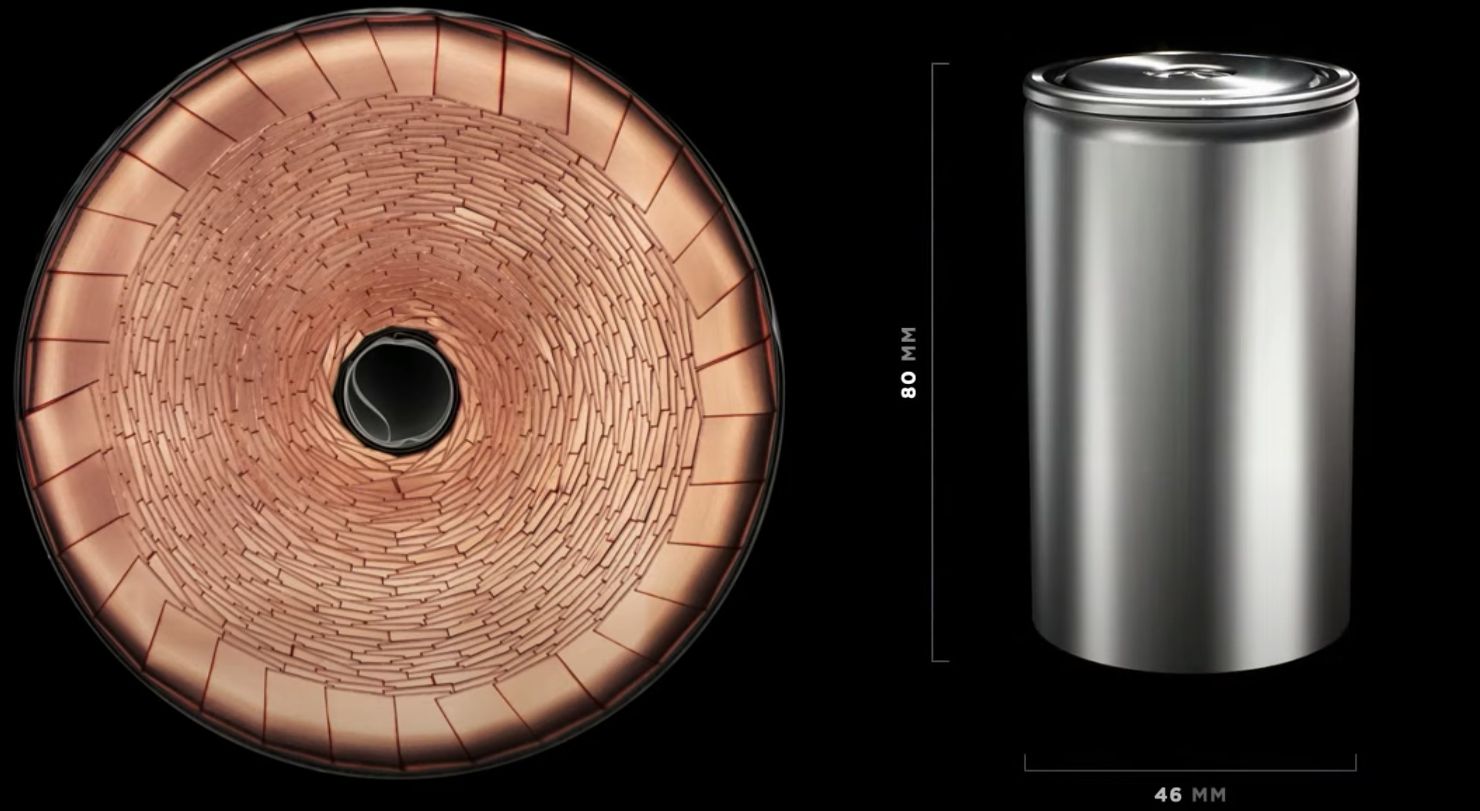
Cylindrical cells benefit from highly automated production methods developed across consumer, industrial, and automotive applications. The regular shape is easy to handle, rotate, inspect, and transport through manufacturing equipment.
Round cells leave spaces when arranged in a rectangular pack. Those spaces reduce the theoretical packing efficiency, but they are not always wasted. Designers can use them for:
- Coolant channels
- Electrical insulation
- Structural adhesive or foam
- Cell holders
- Expansion clearance
- Barriers intended to slow thermal propagation
The pack result depends on how effectively these functions use the available space.
Cylindrical Size Names
Cylindrical designations normally describe the approximate cell diameter and height in millimetres:
- 18650 or 1865: approximately 18 mm in diameter and 65 mm high
- 2170 or 21700: approximately 21 mm in diameter and 70 mm high
- 4680: approximately 46 mm in diameter and 80 mm high
- 4695: approximately 46 mm in diameter and 95 mm high
- 46120: approximately 46 mm in diameter and 120 mm high
Naming conventions are not perfectly consistent. Some manufacturers use five digits, while others omit the final zero. The designation describes the nominal envelope, not the chemistry, capacity, terminal layout, or internal construction.
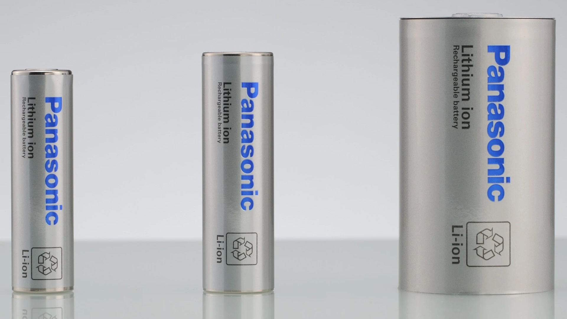
Moving to a larger cylinder reduces the number of cells needed for a given pack capacity. Panasonic states that its 4680 cell has about five times the capacity of its 2170 cell. That is primarily a capacity-per-cell comparison: the 4680 is physically much larger, so it does not mean five times the energy density. (Panasonic Energy)
Larger cells create their own engineering demands. Heat must travel farther from the centre of the jelly roll, current must be collected across larger electrodes, and each cell contains more energy. Manufacturing tolerances, cooling, venting, and propagation protection become increasingly important.
BMW's Gen6 system demonstrates how cells with a common diameter can be adapted to different vehicles. The BMW iX3 uses 46 mm cells with a height of 95 mm, while the BMW iX5 uses cells with the same diameter and chemistry but a height of 120 mm. BMW says the taller cell stores almost 30% more usable energy per cell. The increase comes with the greater cell volume; it is not a 30% increase in energy density. (BMW Group)
Tabs and Current Collection
The coated electrode foils inside a cylindrical cell must connect to the external terminals.
A traditional design uses one or more discrete metal tabs welded to the positive and negative current collectors. Electrons travelling from distant parts of the electrode must move along the thin foil before reaching a tab. That path creates resistance and can produce uneven current and temperature distributions.
Modern large cylindrical cells may use:
- Several tabs distributed along the electrode
- Many small tab sections
- A continuous edge connection around much of the jelly roll
- Full-area connections between the collector edge and terminal assembly
The term tabless is commonly used for continuous-tab designs, but the electrical connection has not disappeared. Instead, a broad part of the current-collector edge acts as the connection. Research on cylindrical-cell current collection shows that additional or better-distributed tabs can reduce temperature rise and thermal gradients. (Journal of Power Sources)
The benefit depends on consistent cutting, folding, welding, and electrical contact around the electrode roll. A clever geometry that is difficult to manufacture repeatably can lose its theoretical advantage.
Cooling Cylindrical Cells
Heat can leave a cylindrical cell through:
- The curved side wall
- The base
- The terminal end
- Conductive material placed between neighbouring cells
Side cooling provides a large contact area but requires cooling structures between rows of cells. Base or terminal cooling can simplify pack assembly, although heat must then travel along the height of the jelly roll.
The electrode roll is thermally anisotropic: heat travels more easily in some directions than others. The best cooling method therefore depends on cell height, diameter, tab design, chemistry, power demand, and the temperature difference the pack can tolerate.
Strengths of Cylindrical Cells
- A rigid enclosure with efficient pressure resistance
- Mature, highly automated production
- Consistent geometry for handling and inspection
- Flexible pack capacity through parallel cell groups
- High surface area relative to energy when smaller cells are used
- Established size families and manufacturing equipment
Limitations of Cylindrical Cells
- Round cells cannot completely fill a rectangular volume
- Small-cell packs require many welds and interconnections
- Large cylinders contain more energy per possible fault
- The pack must create consistent cooling across many cells
- Cell orientation and terminal position constrain pack layout
- Internal core temperature cannot be inferred perfectly from one external measurement
Prismatic Cells
A prismatic cell uses a rigid rectangular enclosure, normally made from aluminium or steel. Its electrode assembly may be a flattened wound roll or a stack of individual layers.
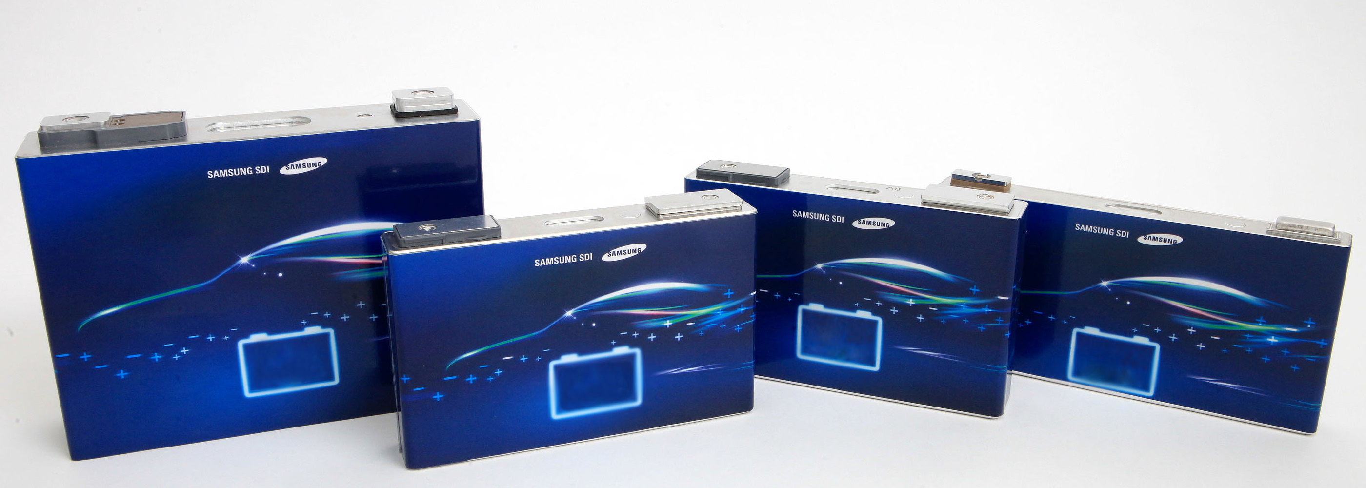
The rectangular shape can use a vehicle's floor area efficiently and allows a pack to be built from relatively few large cells. Fewer cells reduce the number of terminals, busbar joints, welds, and voltage-monitoring points.
Broad cell faces can be placed against cooling plates or compression structures. The metal can also provides impact protection and a defined location for terminals, seals, a pressure vent, and sometimes a current-interrupt or fuse mechanism.
The flat walls need careful mechanical control. Electrode materials change dimensions with state of charge, temperature, and age, while side reactions may generate gas. The pack must permit normal movement while preventing excessive swelling, loss of cooling contact, or damaging local pressure.
Large prismatic cells can also develop internal temperature and state-of-charge gradients. Cooling one face or only the bottom does not guarantee that every part of the electrode stack remains at the same temperature.
Standardised Platforms and Supplier-Specific Cells
Unlike cylindrical cells, prismatic cells do not follow one widely used set of external dimensions. Their height, width, thickness, terminal position, vent design, and capacity are often tailored to a manufacturer or vehicle platform.
This can improve integration but reduces interchangeability. Two prismatic cells with similar chemistry and capacity may not fit the same pack or use the same compression, cooling, and electrical interfaces.
Volkswagen Group's Unified Cell, developed by PowerCo, is an example of standardisation within one vehicle group. It is a prismatic platform intended to support different suppliers, vehicles, and electrode chemistries. PowerCo began production with an NMC version and says LFP variants will follow. (Volkswagen Group)
The Unified Cell is not a new chemistry and does not make all versions electrochemically identical. Electrode materials, loading, capacity, voltage window, charging capability, and thermal requirements can still differ inside a common external concept.
Long Prismatic and Blade-Style Cells
A blade-style cell is a long, narrow prismatic cell. It is not a fourth fundamental format.
BYD's Blade Battery uses long, flat LFP cells placed directly into an array without conventional intermediate modules.
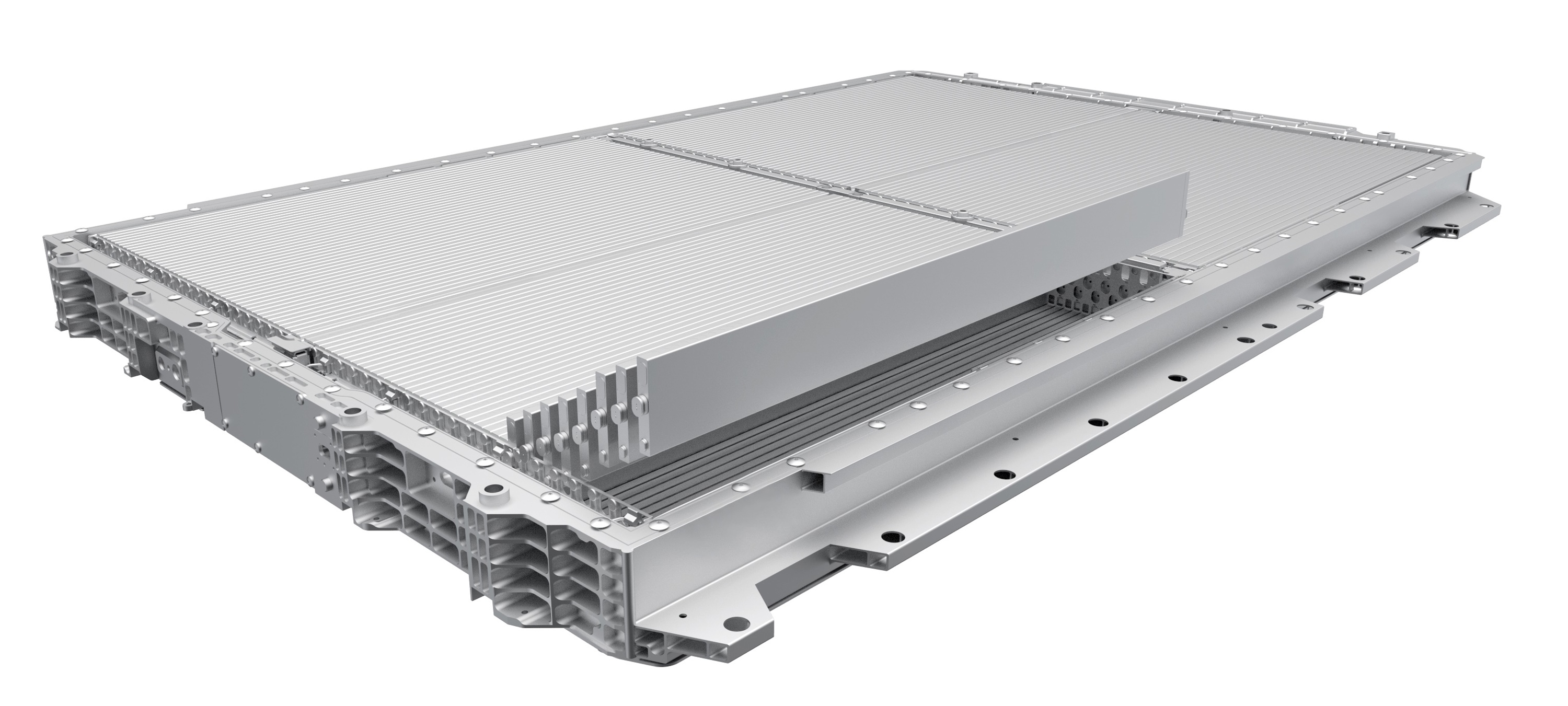
BYD describes each cell as contributing to the pack structure. The long shape lets a cell span a large part of the enclosure, reduces the number of repeated electrical connections, and provides broad surfaces for heat transfer. (BYD)
Many benefits attributed to a blade cell come from the relationship between its dimensions and the pack built around it. A long prismatic cell does not automatically produce high pack energy density, fast charging, or strong crash performance.
Its limitations also come from that close integration:
- Cell length and pack width must be designed together
- Alignment and dimensional tolerances apply across a long component
- Temperature and pressure must remain controlled along the full cell
- One cell contains a substantial amount of energy
- Replacing an individual cell can be difficult in a highly integrated structure
The Blade Battery's thermal behaviour also reflects its LFP chemistry, electrode design, state of charge, and BYD's complete pack system. Cell shape should not be credited for chemistry-related behaviour.
Strengths of Prismatic Cells
- Efficient use of rectangular pack space
- Fewer cells and electrical connections
- Rigid enclosure and defined venting components
- Broad surfaces for cooling and compression
- Dimensions that can be tailored to a vehicle platform
- Good compatibility with module-free pack concepts
Limitations of Prismatic Cells
- Large flat surfaces require controlled expansion and compression
- Internal thermal gradients can develop across a large cell
- Each cell contains considerable energy
- Dimensions and interfaces are often supplier-specific
- A cell designed around one platform may be difficult to reuse elsewhere
- Large cells make the pack more sensitive to the consistency of each cell
Pouch Cells
A pouch cell uses a flexible laminated enclosure instead of a rigid metal can. The film normally combines an aluminium barrier layer with polymer layers that provide electrical insulation, mechanical protection, and heat-sealable surfaces.
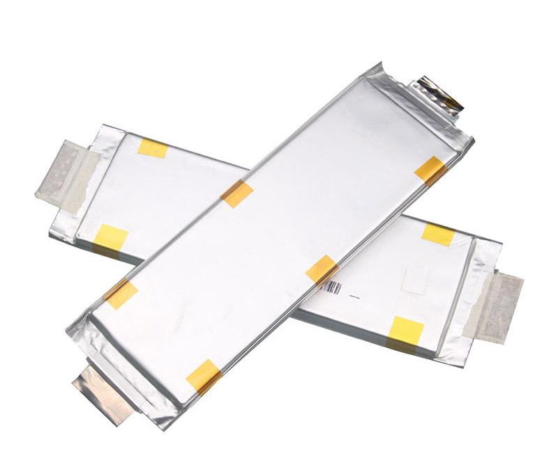
The pouch contains a wound, stacked, laminated, or folded electrode assembly. Large automotive pouch cells often use stacked designs because rectangular layers can occupy the enclosure efficiently.
During LG Energy Solution's pouch-cell assembly process, laminated electrode units are stacked, leads are welded to the stack, and the stack is inserted into a formed pouch. Electrolyte is added through a temporary gas pocket. Gas produced during the first formation cycles is later removed before the pouch receives its final seal. (LG Energy Solution)
The laminated enclosure adds little cell-housing mass, but it does not restrain the electrodes like a rigid can. A pouch cell must be treated as part of a mechanical system that includes:
- Compression plates or frames
- Compliant pads that accommodate expansion
- Protection for the cell edges and lead seals
- A controlled cooling interface
- Barriers between adjacent cells
- Support that prevents bending during assembly and vehicle operation
Pouch cells normally change thickness slightly as they cycle. Additional swelling can occur as the cell ages or if side reactions generate gas. Compression must be strong and uniform enough to maintain contact, but not so high or uneven that it damages the electrode stack.
Cooling Pouch Cells
The broad faces of a pouch cell provide a large potential cooling area. Cooling plates may contact one or both faces, or the pack may remove heat through an edge or the electrode tabs.
Good face contact is essential. If swelling, tolerance variation, or inadequate compression creates a gap, local thermal resistance rises. Pads and thermal-interface materials must maintain contact while allowing normal dimensional changes.
Heat travels more easily along the metal electrode foils than directly through the many electrode and separator layers. A surface temperature can therefore hide a warmer internal region, especially in a large or thick cell.
Strengths of Pouch Cells
- Low enclosure mass
- Efficient use of the internal cell volume
- Flexible width, height, and thickness
- Broad surfaces that can be coupled to cooling plates
- Fewer cells than packs using small cylindrical formats
- Compatibility with stacked electrode construction
Limitations of Pouch Cells
- The pack must provide most of the mechanical support
- Compression and expansion allowance are essential
- Laminated edges and lead seals need careful protection
- Large flexible cells are demanding to handle and assemble
- Swelling can change cooling contact and mechanical pressure
- Frames, pads, and protection offset part of the cell-level weight saving
How Cell Format Changes Pack Engineering
Cell format does not work in isolation. Its value depends on how well the pack architecture uses its strengths and compensates for its limitations.
Cell Count and Electrical Connections
A pack using thousands of small cylindrical cells needs many welds and parallel current paths. A pack using large prismatic or pouch cells needs far fewer connections, but each connection carries more current and each cell represents a larger share of pack capacity.
Fewer cells can simplify sensing and assembly. More cells can provide finer capacity increments and more parallel paths. Neither strategy guarantees reliability: production quality, interconnect design, fault detection, and electrical protection determine the result.
Cooling Paths
Cylindrical cells provide curved surfaces and several possible cooling directions. Prismatic and pouch cells provide broad, flat surfaces but may develop through-thickness gradients.
The cooling system must match:
- Where heat is generated inside the cell
- How readily heat travels through the electrode assembly
- The distance from the warmest internal region to the coolant
- The charging and discharge power
- The acceptable temperature difference between cells
- Cell expansion throughout its life
This is why the same format can perform very differently in two vehicles.
Compression and Structural Support
Pouch cells require external compression. Large prismatic cells also need controlled restraint, even though their cans provide more support. Cylindrical cans are more self-supporting but still need accurate positioning and protection against vibration and impact.
The surrounding structure adds mass and occupies space. Cell-level energy density should therefore not be mistaken for pack-level energy density.
Fault Energy and Propagation
A larger cell contains more energy, so a serious failure can release more heat and gas from one location. A smaller cell contains less energy, but a pack has more neighbouring cells and more possible propagation paths.
Format affects vent direction, spacing, barriers, and heat transfer, but it cannot establish safety on its own. Chemistry, state of charge, cell quality, protection devices, cooling, crash structure, gas management, and propagation testing all matter.
Cell-to-Pack Is Not a Cell Format
Cell-to-pack means that cells are integrated into the pack without conventional self-contained modules. Cylindrical, prismatic, and pouch cells can all be used in module-free designs.
Removing module housings and duplicated structure can improve space and mass efficiency. It also transfers more responsibilities to the pack enclosure, including:
- Cell positioning and restraint
- Electrical isolation
- Cooling contact
- Crash-load management
- Fire and gas management
- Manufacturing tolerance control
- Service and repair strategy
The result depends on the complete design, not simply on deleting the modules.
Manufacturing, Repair, and Recycling
Standardised small cells can simplify cell production while creating a complex pack assembly. Large platform-specific cells can simplify pack assembly while requiring dedicated cell tooling and handling.
Highly integrated packs can reduce parts and weight, but adhesives, structural foams, long cells, and direct cell-to-pack installation may make diagnosis, disassembly, and individual-cell replacement more difficult.
Recycling processes also encounter different housings, adhesives, cooling materials, and disassembly routes. The Department of Energy notes that cell enclosure and electrode assembly influence how easily cells can be opened and processed. (US Department of Energy)
What Cell Format Means for an EV Buyer
Cell format is useful for understanding engineering decisions, but it is not a quality ranking.
A vehicle does not automatically:
- Charge faster because it uses cylindrical cells
- Travel farther because it uses pouch cells
- Last longer because it uses prismatic cells
- Resist thermal propagation because it uses blade-style cells
- Have high pack energy density because it uses cell-to-pack construction
For a specific EV, the more useful questions are:
- What are the gross and usable battery capacities?
- How efficient is the vehicle?
- What does the charging curve look like?
- Can the battery be preconditioned before rapid charging?
- How does charging change in cold or hot conditions?
- How does the thermal-management system cool and heat the cells?
- What degradation and warranty terms apply?
- How has the manufacturer tested propagation between cells?
- Can modules or individual cell groups be diagnosed and replaced?
- Does pack repair require replacing the complete battery?
The format helps explain why a manufacturer selected a particular cooling, structural, manufacturing, or service strategy. The finished vehicle determines whether that strategy works well.
For the materials inside each format, see Cell Chemistry & Components. The electrical connections and structural hierarchy are covered in Battery Pack & Configuration, while cooling systems are explained in Battery Thermal Management.
Sources
- US Department of Energy — Sustainable Manufacturing and the Circular Economy
- Samsung SDI — Cell assembly, winding, and Z-stacking
- Panasonic Energy — 4680 automotive lithium-ion battery production
- BMW Group — Gen6 cylindrical cells in the BMW iX5
- Journal of Power Sources — Cylindrical-cell tab design and cooling strategy
- Volkswagen Group — Start of PowerCo Unified Cell production
- BYD — Blade Battery design
- LG Energy Solution — Pouch-cell assembly