
How WLTP EV Range Is Calculated
WLTP range is the end of a controlled measurement chain, not the distance covered by one lap of a cycle. The chain joins a defined vehicle configuration, road load, battery depletion, measured electrical energy and regulated calculations.
WLTC is the trace; WLTP is the procedure
The Worldwide harmonized Light vehicles Test Cycle, WLTC, tells the dynamometer operator how vehicle speed must change with time. The Worldwide harmonized Light vehicles Test Procedure, WLTP, defines the wider test system: vehicle classification, test mass, road-load determination, laboratory conditions, battery preparation, measurement, calculations, interpolation and conformity requirements.
For the high-performance passenger cars that make up most current EV comparisons, the Class 3b WLTC has four phases:
- low: 589 seconds;
- medium: 433 seconds;
- high: 455 seconds;
- extra-high: 323 seconds.
Together they last 1,800 seconds, cover approximately 23.27 km and reach 131.3 km/h. The mean speed including stops is about 46.5 km/h. Those numbers describe the trace, not a 23 km limit on EV testing. A battery-electric vehicle must be depleted far enough to determine the usable battery energy and energy consumption required for its range calculation. UNECE: UN Regulation No. 154, Worldwide harmonized Light vehicles Test Procedure
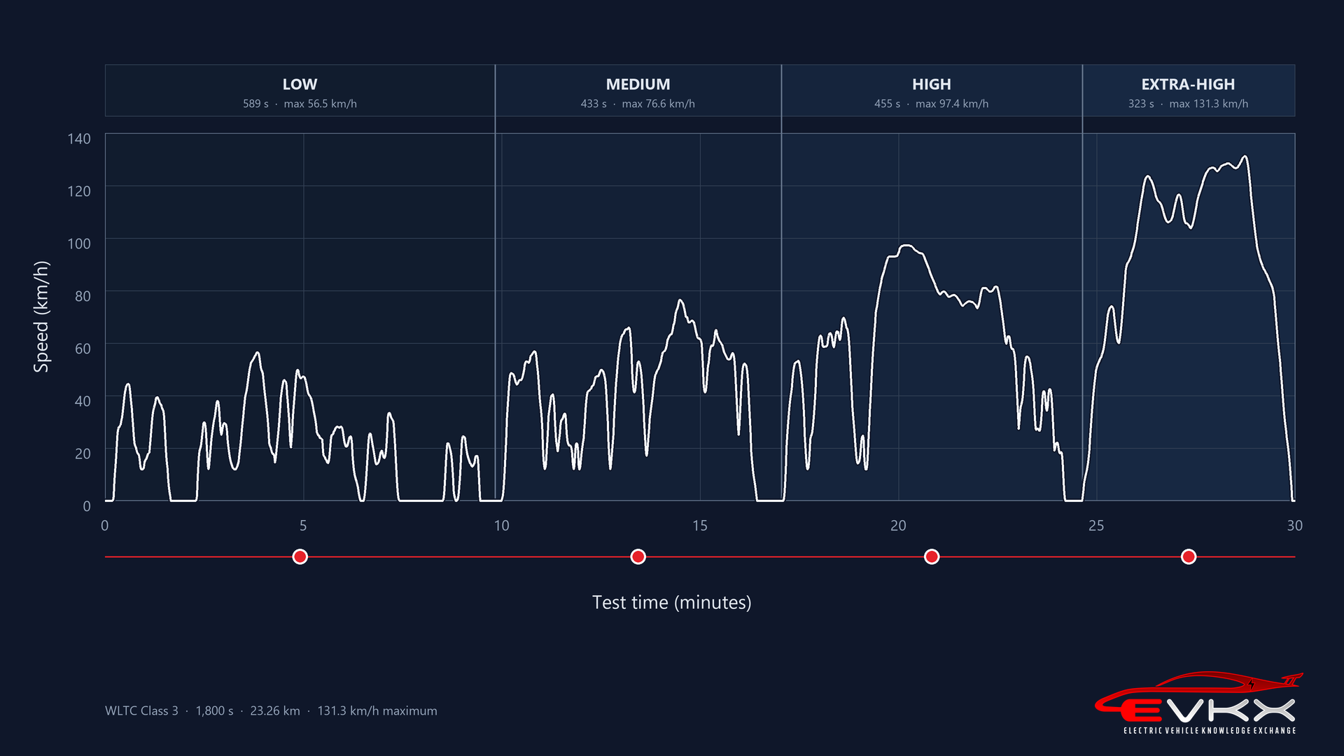
The distinction also prevents a common error: a Japanese value described as “WLTC” need not use the same four-phase combination as a European WLTP value. Market implementation rules decide which phases and calculations become the declared figure.
Step 1: define the certified vehicle
An EV type can have several wheel sizes, tyres, trim levels and option combinations. Testing every possible build would be impractical, but publishing one best-case result for all of them would be misleading.
WLTP therefore uses vehicle families and, where permitted, interpolation. Vehicle H represents the configuration with the higher cycle energy demand within an interpolation family; Vehicle L represents the lower-demand configuration. The tested boundary vehicles and their road-load and energy results form the basis for calculating values for individual configurations between them.
Mass is configuration-specific. The procedure starts from the vehicle’s mass in running order and adds regulated load elements to obtain the applicable test mass. Aerodynamic and rolling-resistance differences from wheels, tyres and equipment are reflected through road load, declared data and the family rules.
This is why two versions with the same battery and motors can have different WLTP ranges. A larger wheel may raise rolling resistance, change frontal airflow and increase rotational losses. Added equipment may increase mass or cooling demand. The certified value belongs to a defined configuration or interpolated position, not merely to a model name.
Step 2: determine road load
The WLTC specifies speed against time, but it does not tell the dynamometer how much force a particular vehicle must overcome. That force is established separately as road load.
The represented configuration is prepared at its applicable test mass with the specified tyres, tyre pressure, wheel alignment, ride height and aerodynamic state. A common determination method is a road coastdown: the warmed vehicle is allowed to decelerate in neutral or a dedicated coastdown mode while speed and elapsed time are recorded. Runs in opposite directions and regulated corrections reduce the effect of wind, gradient, air density and temperature.
The resulting target is commonly represented as:
F(v) = f0 + f1 × v + f2 × v²
The lower-order terms contain much of the rolling, bearing and driveline resistance. The quadratic term is dominated by aerodynamic drag. Vehicle shape therefore enters the WLTP result before the vehicle follows the WLTC: a larger frontal area, less favourable drag coefficient, open cooling path, different wheel airflow or higher ride height can increase the road-load curve.
The target road load is then translated into dynamometer settings. The rollers and tyres already create some laboratory resistance, so the electric absorber supplies the additional force needed for the complete system to match the road target. A dynamometer coastdown is used to verify the setting within the prescribed tolerance. A cooling fan may move air over the stationary vehicle, but the calibrated aerodynamic load is reproduced by the rollers rather than by relying on fan force. UNECE: UN Regulation No. 154, Worldwide harmonized Light vehicles Test Procedure EUR-Lex: Commission Regulation (EU) 2017/1151, consolidated WLTP requirements
Road load is also central to WLTP interpolation. Vehicle H and Vehicle L define higher- and lower-demand boundaries for eligible configurations, and the declared value for an individual build is calculated within that regulated family. Wheels, tyres, equipment and active aerodynamic devices must therefore be represented through the applicable test, calculation and family rules.
An understated road load would reduce the battery energy measured over every phase, with the largest aerodynamic effect in the high and extra-high phases. The regulation controls vehicle preparation, data processing, coastdown and dynamometer verification because this input is too influential to leave undefined.
Step 3: prepare the battery and laboratory
The vehicle is fully charged using the prescribed procedure, conditioned and soaked before testing. The normal-temperature procedure is conducted around 23°C under controlled laboratory conditions. The exact sequence includes tolerances, breaks and termination rules; it is not equivalent to starting an owner’s car on an arbitrary day at 23°C.
The vehicle follows its applicable driver-selectable mode rules. Accessories and climate loads are controlled by the procedure rather than chosen to imitate a particular family journey. The resulting figure should therefore be read as a standardized comparison at normal test temperature, not as a winter-range forecast.
Separate low-temperature procedures are a developing part of the regulatory framework, but they should not be silently mixed with the familiar headline combined WLTP range. The test name, temperature condition and value type must travel with the number.
Step 4: deplete the battery
The regulation provides a conventional consecutive-cycle test and a shortened test procedure for battery-electric vehicles.
In the consecutive-cycle route, the vehicle repeats the applicable cycle sequence as the battery state of charge falls. The final cycle is treated according to the prescribed break-off and calculation rules. This route is conceptually direct, but a long-range EV may need many repeated cycles and many hours of laboratory time.
The shortened test procedure reduces that time while retaining measured cycle segments at high and low battery state of charge. Its broad sequence is:
- Start from a fully charged, conditioned battery.
- Drive the first WLTC segment at high state of charge.
- Use a regulated constant-speed segment, at least 100 km/h where the vehicle permits, to remove energy more quickly.
- Drive another WLTC segment at low state of charge.
- Continue to the prescribed battery break-off criterion.
- Recharge and record the required energy data.
The middle constant-speed section is not counted as if it were ordinary WLTC driving. It is a time-saving depletion segment. The measured WLTC segments are used to establish cycle energy consumption, while the full test establishes usable battery energy. The detailed equations account for distance, state-of-charge change and the incomplete final segment. The shortened procedure was developed specifically to avoid forcing increasingly long-range EVs through dozens of identical cycles. UNECE: Development of the WLTP shortened test procedure for electrified vehicles
Exactly when does the WLTP depletion test stop?
The dashboard reaching 0% is not the break-off criterion. In the shortened procedure, the endpoint is reached when the vehicle exceeds the prescribed speed-trace tolerance for four consecutive seconds or more in the second, end-of-test constant-speed segment. The accelerator control is then deactivated and the vehicle is brought to a standstill within 60 seconds. UNECE: UN Regulation No. 154, Worldwide harmonized Light vehicles Test Procedure UNECE: Development of the WLTP shortened test procedure for electrified vehicles
This is an operational endpoint at a defined power demand. It does not mean that the cells have reached electrochemical zero. The battery-management system retains a protective margin above the damaging lower-voltage region.
If the dashboard reaches 0% before the car loses the ability to follow the final trace, the DC energy used after displayed 0% remains part of the measured depletion test. If propulsion is restricted before every last watt-hour that could be extracted at a gentler load, the test stops with some energy still physically present.
The distinction matters because terminal voltage falls under load. Near the lower state-of-charge limit, a battery might still sustain slow driving but be unable to meet a higher speed or acceleration request. Using a controlled constant-speed segment near the cutoff reduces this source of variability compared with ending at an arbitrary point in a dynamic cycle.
Step 5: measure usable battery energy
During the depletion test, DC battery voltage and current are measured. Integrating DC power over time gives the energy removed from the rechargeable energy storage system under the procedure.
In simplified form:
DC energy = integral of battery voltage × battery current over time
The resulting usable battery energy is procedural. It depends on the prescribed full-charge condition and battery break-off criterion. It is not automatically the battery’s advertised gross capacity, and it need not equal the displayed 100-to-0 energy available to a driver under every condition.
A measured WLTP usable-energy value can include a reserve below displayed 0% when the vehicle remains capable of completing the prescribed trace. It excludes energy protected below the propulsion cutoff. The usable-energy number alone cannot reveal the below-zero reserve; that requires the displayed state of charge or battery-management data to be recorded alongside the DC discharge.
After depletion, the vehicle is recharged under the regulated sequence. AC energy from the electricity supply can be measured for electric-energy-consumption reporting, which captures charging losses. The range calculation itself uses the regulated relationship between usable battery energy and DC cycle consumption. A WLTP consumption value must therefore be identified as DC- or AC-based before it is used to reverse-engineer a battery capacity.
Step 6: calculate cycle consumption and range
The shortened procedure combines the measured energy consumption from the high- and low-state-of-charge WLTC segments using the regulation’s weighting method. In simplified notation:
WLTC electric range = usable battery energy / weighted WLTC DC consumption
If usable battery energy is expressed in kWh and consumption in kWh/km, the quotient is kilometres. The actual regulation includes the prescribed phase, correction, weighting, break-off and rounding provisions; the short equation shows the physical relationship, not a substitute homologation calculation.
The combined value uses the full applicable phase combination. A city value is derived from the urban portions, principally the low and medium phases for the applicable passenger-car cycle. Each value answers a different speed-profile question.
For an interpolation family, the tested Vehicle H and Vehicle L results are used to determine the declared value for each configuration. The manufacturer submits declared values, but they must satisfy the procedure’s relationship to measured results and the approval authority’s validation and conformity requirements. WLTP is a regulated type-approval system, not an unrestricted manufacturer estimate.
Why WLTP often differs from motorway range
The cycle includes stops, low-speed operation and regenerative opportunities. Its extra-high phase reaches motorway speed, but the complete 30-minute weighting is not a continuous 120 or 130 km/h cruise. At steady high speed, aerodynamic power can dominate and there may be little braking energy to recover.
The normal-temperature test also excludes the sustained cabin and battery-heating demand of many winter journeys. Conversely, dense urban driving in mild weather can allow an efficient EV to exceed its combined WLTP distance.
The gap is vehicle-specific. A fixed rule such as “subtract 20%” discards the very differences a useful comparison should reveal.
How to compare WLTP values
Check that both numbers are:
- from the same market implementation and test generation;
- either combined or city values, not one of each;
- for the relevant wheel, tyre and powertrain configuration;
- certified rather than provisional;
- expressed with the same consumption boundary if energy use is compared.
WLTP is strongest as a controlled comparison between like-for-like configurations. It becomes weaker when treated as a promise for a route whose speed, weather and thermal loads bear little resemblance to the procedure.