
DC Fast Charging
DC fast charging moves the main power conversion out of the car and into the station. It can add journey energy quickly, but the useful result depends on the complete site, station, cable, vehicle, battery, and charging-network chain.
The DC power path
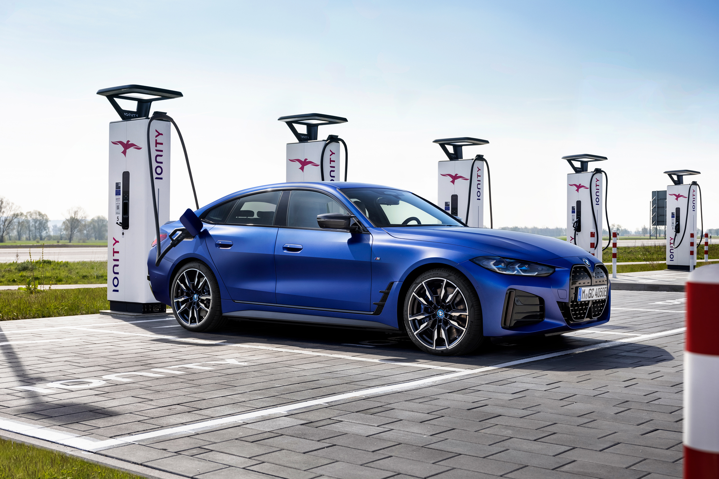
A public fast-charging site typically contains more hardware than the visible dispenser:
- A grid connection, transformer, and switchgear supply the site.
- Power cabinets rectify AC into controlled DC.
- Conversion modules may be shared among several dispensers.
- A liquid-cooled or naturally cooled cable carries DC to the vehicle.
- Contactors, insulation monitoring, and protective systems keep high voltage isolated until checks pass.
- The vehicle requests voltage and current within its safe limits.
- The station meters energy and reports the transaction to a charging-network backend.
Some sites add a stationary battery to reduce grid peaks, support a limited connection, or shift when energy is drawn from the grid. That battery does not create energy; it must be recharged, and sustained site output still depends on the grid connection and operating strategy.
What happens after the plug is inserted
The exact sequence varies by charging system, but a modern DC session follows the same safety logic:
- The station detects the connector and vehicle.
- Low-voltage signalling confirms connection state and cable capability.
- The station and vehicle establish high-level communication.
- The driver or vehicle is authorized, unless the station starts without account authentication.
- The systems check isolation, locking, voltage compatibility, and fault state.
- The station raises its output to match the vehicle side before the high-voltage path closes.
- The vehicle repeatedly requests a permitted current and voltage.
- Both sides monitor current, voltage, insulation, connector temperature, emergency inputs, and communication.
- At stop, current falls, contactors open, voltage is discharged as required, and the connector unlocks.
This negotiation explains why a physically compatible plug is necessary but insufficient. A session can fail before power transfer because of communication, certificates, station backend, authorization, insulation checks, lock detection, or incompatible voltage.
The advertised number is a ceiling
A “350 kW charger” label may describe the cabinet, one dispenser under ideal conditions, or the maximum of a power-sharing group. It does not promise 350 kW to every connected vehicle.
Instantaneous output is bounded by:
- Site power available at that moment
- Conversion-module allocation
- Station maximum voltage and current
- Cable and connector continuous or boost current
- Cooling and contact temperature
- Vehicle inlet, conductors, and power electronics
- Battery voltage and the current requested by the vehicle
Power is voltage multiplied by current. A station limited to 500 A can ideally supply 200 kW at 400 V, 350 kW at 700 V, or 450 kW at 900 V. A lower-voltage vehicle may therefore be current-limited even when connected to a dispenser with a much higher advertised kilowatt rating.
Power sharing can be static, dynamic, or module-based. A site may divide a cabinet evenly, route free modules to the car that can use them, or cap total output because of transformer or battery limits. Station screens and apps do not always explain which limit is active.
Judge a car by energy added and time
Peak power is easy to advertise and often a poor journey metric. A fair comparison identifies:
- Starting and ending state of charge
- Kilowatt-hours added
- Elapsed charging time
- Average power over that exact window
- Battery and ambient temperature
- Preconditioning state
- Station voltage and current capability
- Whether the value is measured, certified, or manufacturer-claimed
Adding 60 percentage points to a 120 kWh battery transfers much more energy than adding 60 percentage points to a 60 kWh battery. Two “10–80%” times are not comparable without the energy added.
Average power for a session window is:
Average power = energy delivered ÷ elapsed time
If 56 kWh reaches the vehicle in 18 minutes, the average station output is about 187 kW:
56 kWh ÷ 0.3 h ≈ 187 kW
The meter-to-battery distinction still matters. Station-delivered energy can exceed energy stored because the vehicle uses power for pumps, fans, heating, cooling, electronics, and internal losses.
Battery temperature, charge curves, C-rate, voltage architecture, and repeated-session thermal behaviour are explained in How an EV Battery Charges. This article treats the station and journey boundary rather than repeating that battery theory.
Arrive low, but not without a margin
Many EVs accept their highest DC power at a relatively low state of charge, then reduce power as the battery fills. Route planning can exploit that by arriving with a low but safe reserve and charging only enough to reach the next suitable stop.
The lowest theoretical arrival percentage is rarely the best target. Allow for:
- Weather and wind
- Elevation
- Detours and road closures
- Towing or roof loads
- Charger failure or queue
- A cold battery or missed preconditioning
- The energy needed to reach an alternate site
Leaving at 80% is not a universal rule either. If power remains strong, the next reliable station is distant, or conditions are poor, charging beyond 80% can be rational. If power has fallen sharply and another reliable site is close, leaving earlier may shorten the trip.
Vehicle efficiency connects charging speed to road speed. A car adding energy at 180 kW but consuming 30 kWh/100 km gains distance at the same rate as a car adding at 120 kW and consuming 20 kWh/100 km, before other differences. Kilowatts alone do not determine journey pace.
Preconditioning and repeated stops
Selecting a compatible DC station in the vehicle's navigation can allow the car to prepare its battery before arrival. Manual preparation, route-based automation, or scheduled departure may also be available.
Preconditioning needs time and energy. It cannot overcome an incompatible station, a very high arrival state of charge, site power sharing, or a battery outside the vehicle's controllable temperature range. A charger entered only through a phone app may not trigger the car's route-based preparation.
For long journeys, repeatability matters. High-speed driving, towing, summer heat, and several consecutive charging stops load the cooling system. A vehicle with a moderate but stable curve can outperform one with a higher first-session peak that cannot be repeated.
Coverage is more than map pins
A station marker does not prove a useful charging stop. Route planning should consider:
- Number of independently usable stalls
- Connector and voltage compatibility
- Cable reach and parking orientation
- Current station status and recent reliability
- Power sharing
- Opening hours and physical access
- Trailer-friendly or pull-through spaces
- Lighting, weather protection, toilets, and food
- Mobile coverage and alternative authorization
- Price, idle fees, and parking restrictions
- A credible fallback site
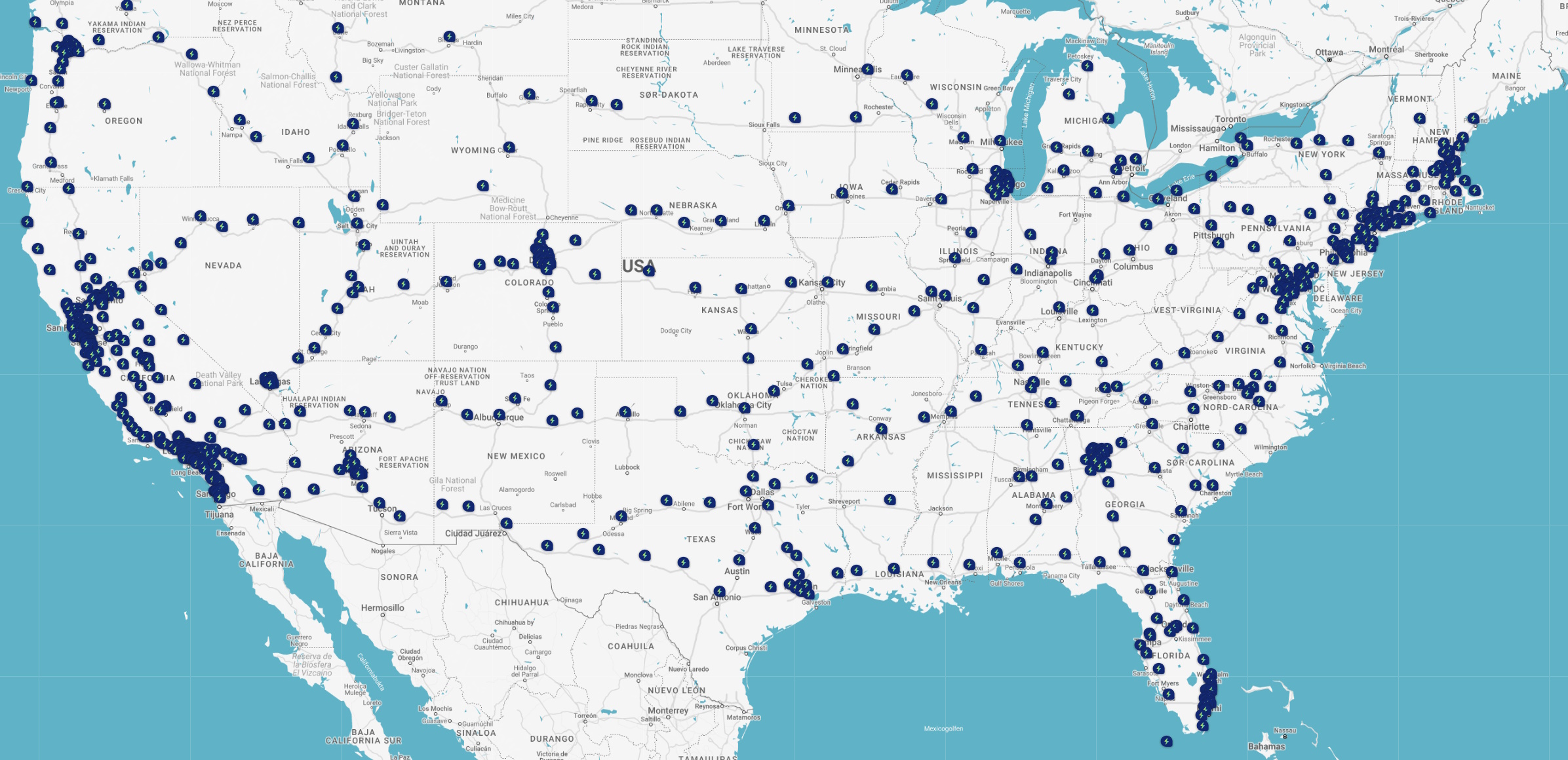
The following map is a historical snapshot from June 2023. It illustrates network geography, not current Electrify America coverage.
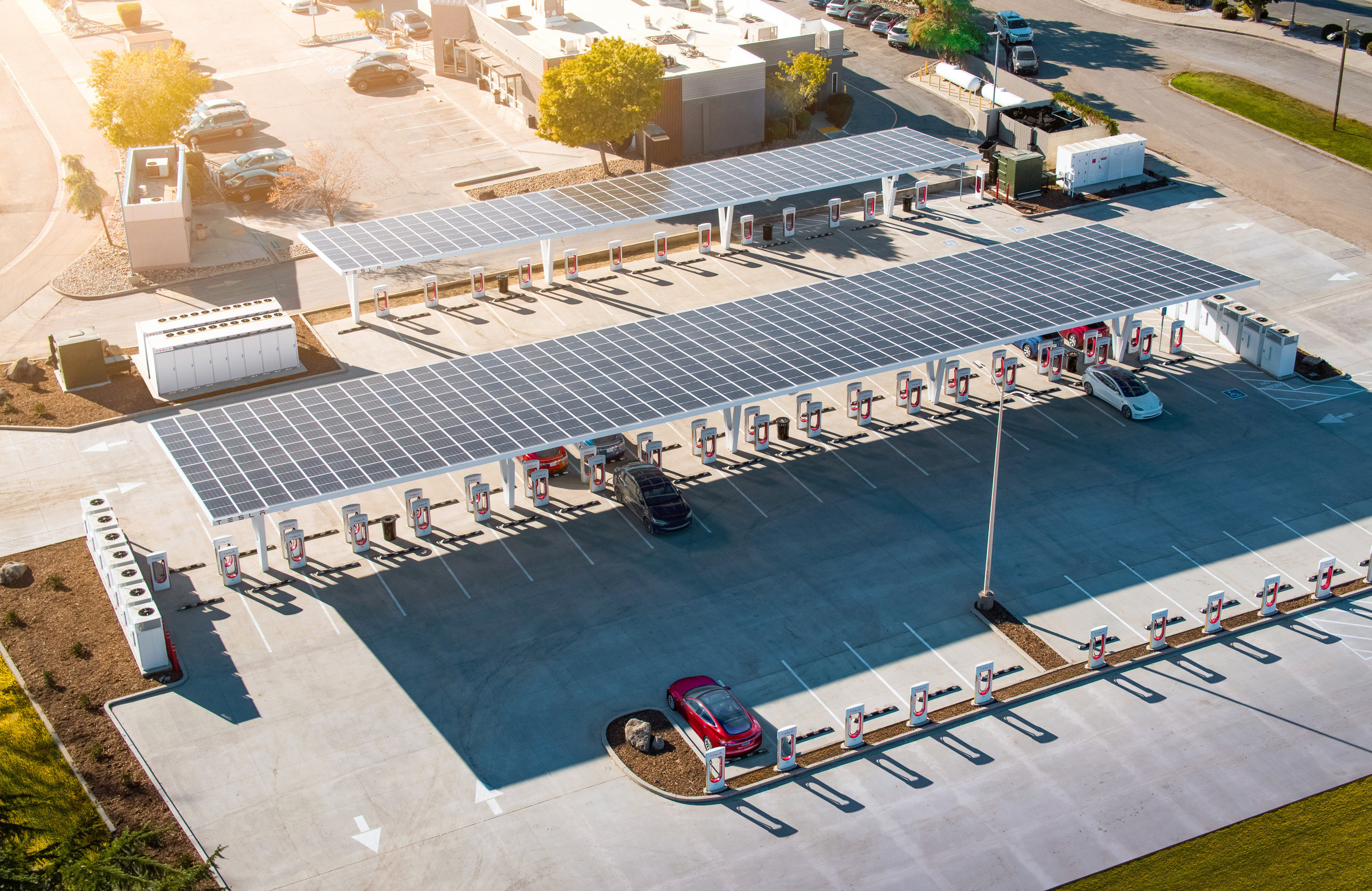
Networks can differ in site design as much as in scale. Tesla's integrated vehicle, route-planning, and Supercharger ecosystem reduced several compatibility variables for its own vehicles. Open access and SAE J3400 adoption expand the possible vehicle set, but station generation, adapter approval, voltage, cable reach, and network authorization still determine the result.
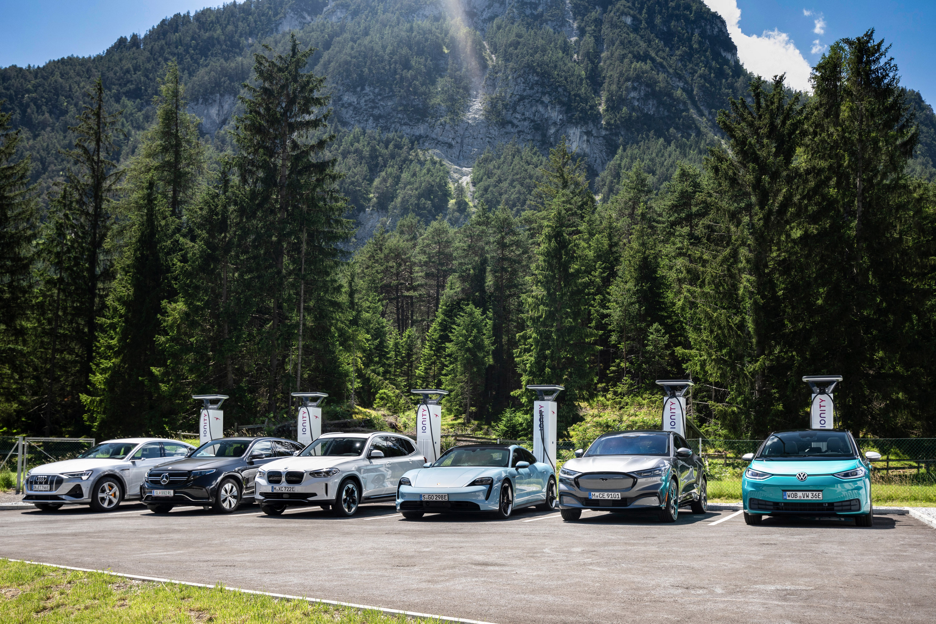
IONITY is an example of a European high-power CCS network designed around major travel corridors. A driver's practical assessment should still be site-specific rather than assuming that every location has identical equipment or availability.
Authentication, payment, and protocols
Several communication boundaries coexist:
- Vehicle-to-station communication controls the energy transfer.
- ISO 15118 Plug & Charge can use vehicle-held contract certificates for automatic authentication and billing.
- OCPP connects a charge point with its management system for authorization, transactions, monitoring, configuration, and smart charging.
- Roaming systems connect mobility providers and charging operators.
- A payment terminal, app, RFID credential, QR flow, or bank card may provide ad hoc authorization.
Supporting one layer does not guarantee the others. A station can implement OCPP without vehicle-based Plug & Charge, and a car can support ISO 15118 while a network lacks the necessary certificate and contract ecosystem.
EU rules provide a useful example of customer-facing requirements: public sites deployed under the applicable provisions must support ad hoc payment, and stations at or above 50 kW must show an ad hoc energy price per kWh plus any occupancy fee before the session. Rules in other markets differ.
Drivers should compare the final tariff, not only the electricity component. Session fees, time charges, roaming markups, membership plans, parking charges, and idle fees can change the total.
If a session will not start
A disciplined check is faster than repeatedly reconnecting:
- Read the station and vehicle messages before dismissing them.
- Confirm the connector is fully seated and the cable is not pulling sideways.
- Try the station's stop command, unlock the vehicle, then reconnect once.
- Check whether the station requires app, RFID, bank-card, or Plug & Charge authorization.
- Try another dispenser at the same site; it may use different power modules or cable hardware.
- If safe and practical, move to a nearby alternative rather than exhausting the reserve.
- Report the exact stall, connector, time, and error to the operator.
Do not use improvised adapters, hold a damaged connector in place, defeat a lock, or continue after visible arcing, exposed conductors, liquid ingress, smoke, or severe connector heat. Use the station emergency stop only for an emergency, not as the normal way to end a session.
Connector families and adapter limits are covered in EV Charging Connectors and Inlets. The complete system overview is EV Charging: The Complete System.
Sources
- U.S. Alternative Fuels Data Center — Electric vehicle charging stations
- CharIN — Combined Charging System architecture and implementation
- CharIN — Plug & Charge and ISO 15118 interoperability
- Open Charge Alliance — Open Charge Point Protocol
- EU Regulation 2023/1804 — Alternative fuels infrastructure