
EV Charging Connectors and Inlets
A charging connector is one layer of an electrical and digital interface; the wider power path is explained in EV Charging: The Complete System. The plug can fit while the session still fails because voltage, current, communication, authorization, software, or adapter support is incompatible.
Connector, inlet, port, and coupler
Precise terms help:
- The vehicle connector is the cable-end device inserted into the car.
- The vehicle inlet is the matching fixed receptacle on the car.
- The coupler is the connector-and-inlet pair.
- The charge port usually means the complete vehicle assembly, including the inlet, door, lock, lighting, temperature sensors, and nearby control hardware.
The physical contacts carry power and safety signals. Depending on the system, additional communication may use dedicated pins, control-pilot signalling, power-line communication, or CAN. A complete charging standard also defines connection sequencing, locking, insulation checks, current limits, temperature response, and fault behaviour.
North American interfaces
SAE J1772 Type 1
SAE J1772 Type 1 is the established North American AC interface. It uses two power contacts for single-phase AC, a protective-earth contact, a control pilot, and a proximity circuit. The pilot tells the vehicle how much current the EVSE can provide; the proximity circuit helps detect the latch and cable state.
The connector's standard rating is not the car's charging rate. Actual AC power is limited by the supply, EVSE, cable, and vehicle onboard charger.
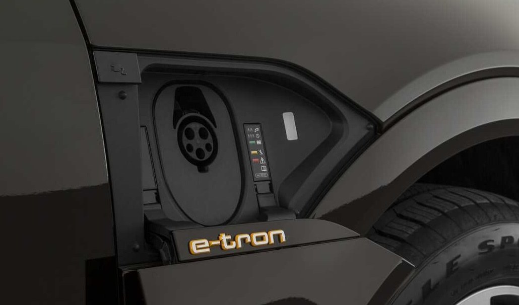
CCS Combo 1
CCS Combo 1 adds two large DC contacts below the J1772 section. An AC J1772 connector uses only the upper portion; a Combo 1 DC connector mates with both sections. The combined inlet lets one vehicle location support AC and DC without two unrelated charge ports.
CCS is more than the shape of the plug. The complete Combined Charging System includes control-pilot behaviour, high-level communication, safety sequencing, charging control, and optional functions such as Plug & Charge.
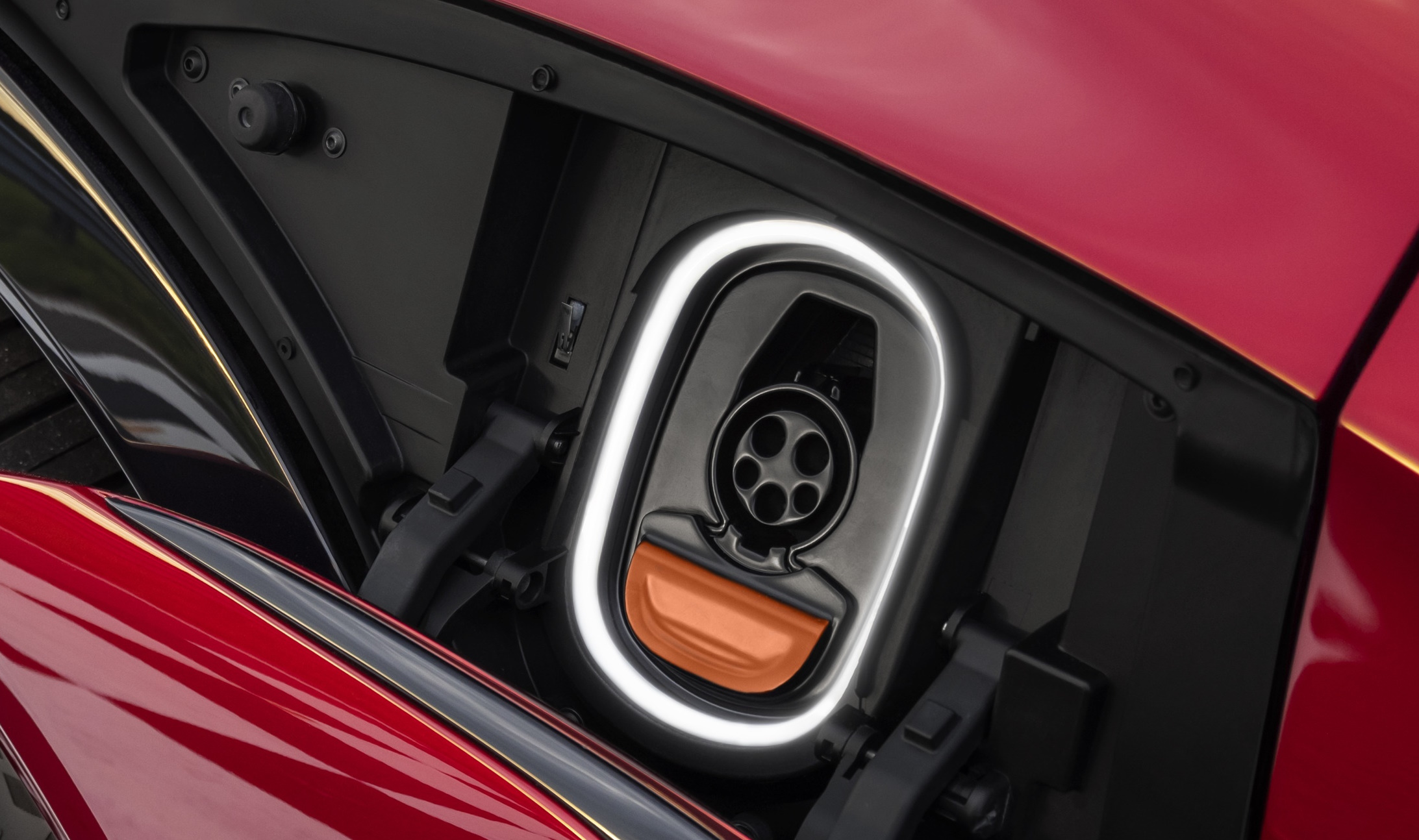
SAE J3400
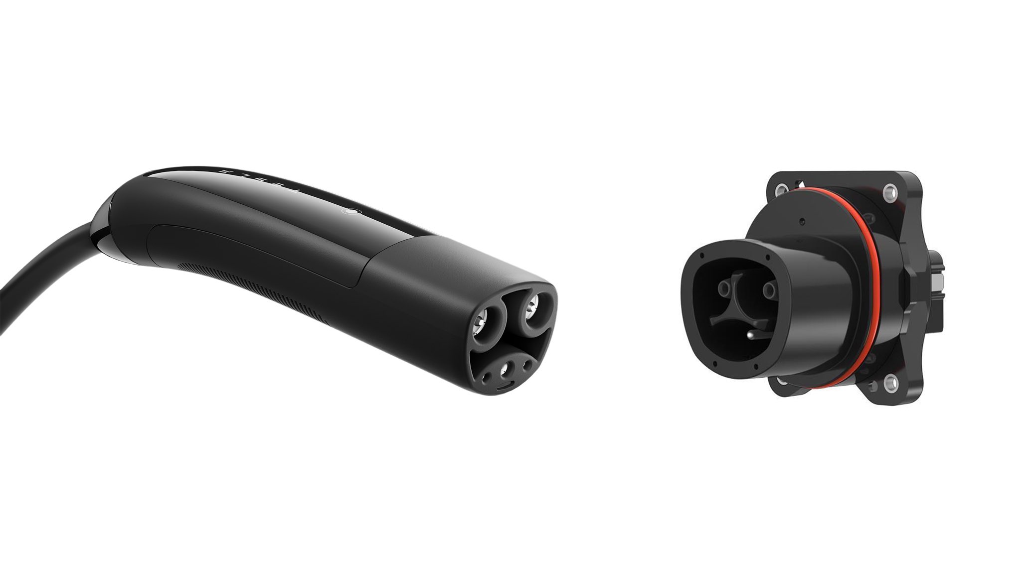
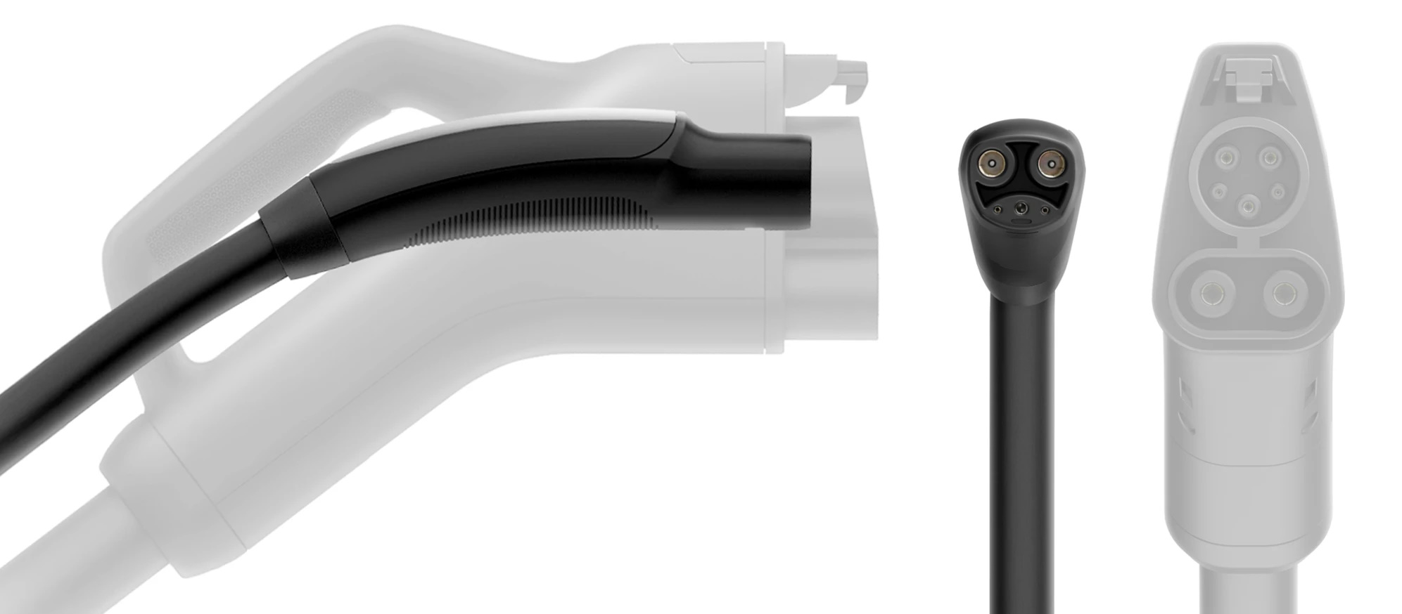
The interface originally opened by Tesla as the North American Charging Standard is now standardized through the SAE J3400 family. SAE J3400 uses the same two main power contacts for AC or DC transfer, with separate control and proximity contacts. The compact coupler does not by itself determine the station's power, voltage range, communication implementation, or which vehicles a network authorizes.
J3400 adoption does not make every car immediately compatible with every former Tesla Supercharger. Vehicles, stations, cable reach, network access, voltage support, and software generations still matter.
European interfaces
IEC Type 2
Type 2 is the principal AC interface for passenger EVs in Europe and other IEC-based markets. Its contact arrangement supports single-phase or three-phase AC, control-pilot signalling, proximity detection, and protective earth. IEC 62196-2:2025 defines standardized AC accessories up to 480 V AC and specified current limits, but most passenger cars accept far less than the connector's maximum envelope.
European public AC stations often provide an untethered Type 2 socket, so the driver carries a Type 2 cable. Home wallboxes and higher-use locations may instead have a tethered cable.
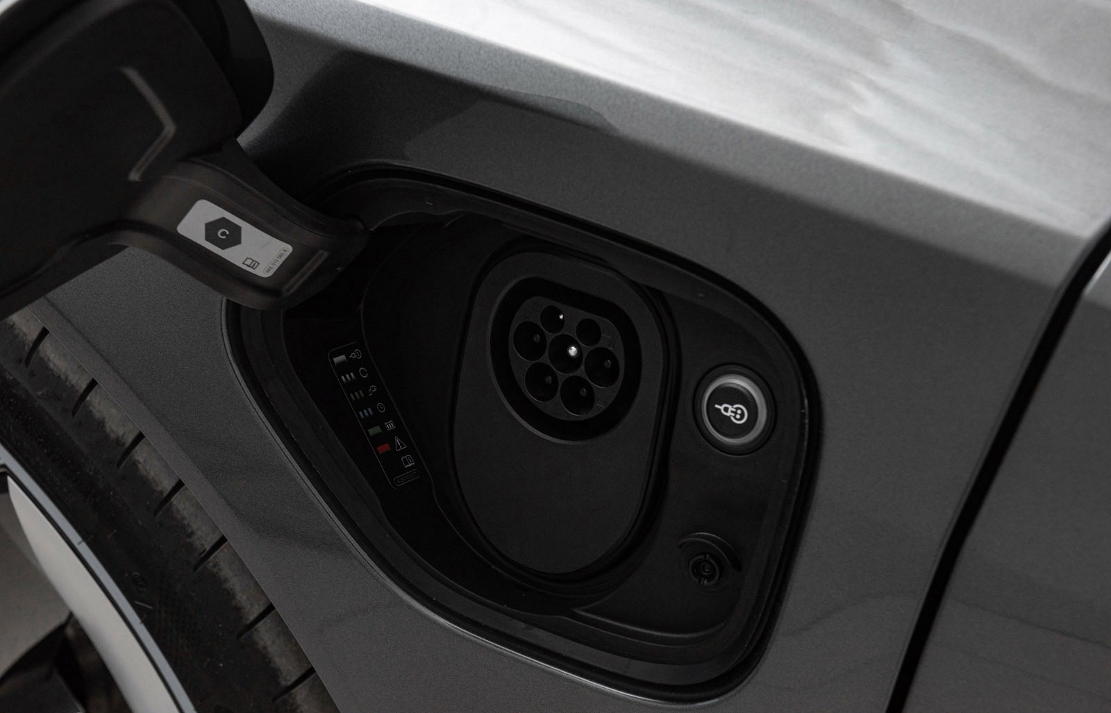
CCS Combo 2
CCS Combo 2 adds two DC contacts below the Type 2 section. As with Combo 1, the upper part supports the control and communication functions while the large lower contacts carry DC.
EU interoperability rules require at least Type 2 for relevant public AC charging and Combo 2 for relevant public DC charging. That requirement explains the regional dominance of these interfaces; it does not prevent a site from also offering another connector.
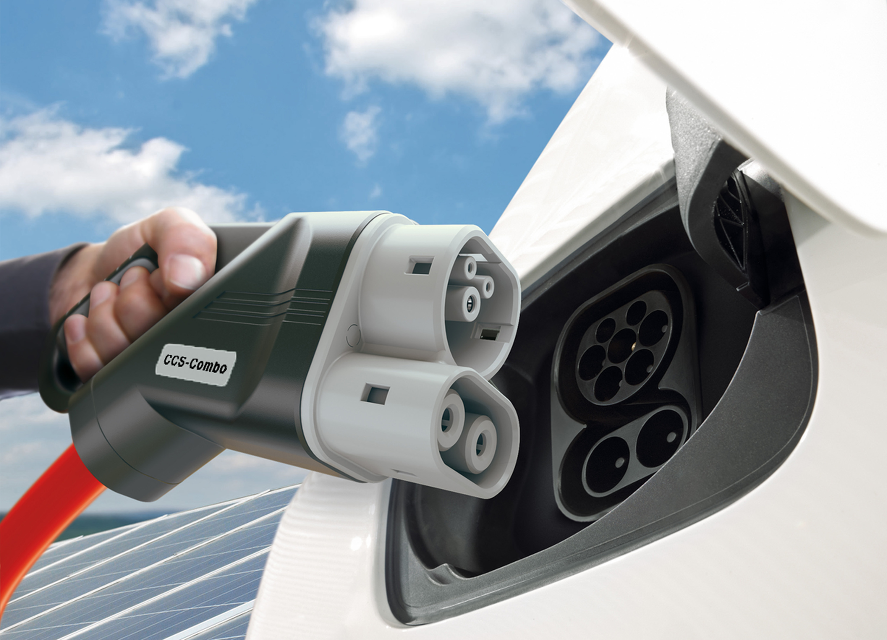
Japanese and Chinese interfaces
CHAdeMO
CHAdeMO is a DC charging system historically used by Japanese EVs and several export models. Many vehicles pair a separate CHAdeMO inlet with an AC inlet. Communication for the established system uses CAN rather than the power-line communication used by CCS.
Installed CHAdeMO vehicles and chargers span several protocol generations and power levels. The CHAdeMO Association released protocol version 2.1 in 2026 with an envelope up to 800 A and 800 kW for the existing connector configuration, while CHAdeMO 3.0/ChaoJi defines a different high-power interface. Those standard ceilings must not be mistaken for the capability of existing passenger cars or roadside chargers.
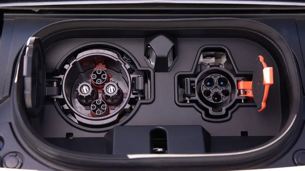
GB/T and ChaoJi
China's GB/T system uses its own AC and DC couplers. The 2023 revision of the established DC interface retained backward physical compatibility while adding requirements for higher current, active cooling, temperature monitoring, and power up to the standard's specified envelope.
GB/T 20234.4-2023 defines a separate high-power DC coupler associated with the ChaoJi architecture. ChaoJi was developed to support higher power with a smaller liquid-cooled connector and a path toward adapters for earlier systems. A ChaoJi connector, legacy GB/T DC connector, and CHAdeMO connector are not physically interchangeable merely because their standards work shares technical ancestry.
A connector rating is not charging performance
The maximum number attached to a connector is normally a test or design envelope under stated voltage, current, cooling, and temperature conditions. Real power can be lower because of:
- The station's conversion modules and output-voltage range
- Continuous versus temporary cable-current limits
- Connector and inlet temperature
- Site-level or cabinet-level power sharing
- Vehicle contactors, conductors, and charge-port cooling
- Battery voltage and requested current
- A protocol, firmware, or certification limitation
Power also changes with voltage. A cable capable of 500 A supplies 200 kW at 400 V and 400 kW at 800 V in an idealized calculation. Marketing a connector as “500 kW capable” without the voltage and current conditions is incomplete.
What an adapter can and cannot do
An adapter can rearrange a compatible electrical interface; it cannot create missing vehicle hardware or translate every charging system automatically.
For AC charging, a passive adapter may be sufficient when the voltage, phase arrangement, pilot signalling, current, earthing, and local approval all match. For DC charging, compatibility also depends on communication, station authorization, cable and inlet temperature monitoring, locking, isolation, and the vehicle manufacturer's software.
Use an adapter explicitly approved for the vehicle, charging system, market, and current. SAE J3400/1 addresses safety and OEM-qualified designation for certain J3400-to-J1772 adapters. Extension leads, stacked adapters, and improvised transition pieces add contact resistance, defeat locking assumptions, or bypass temperature protection.
Port location changes the charging experience
The best inlet position depends on how sites are laid out. Cable reach can be more limiting than connector compatibility, particularly with older stations built around one vehicle layout.
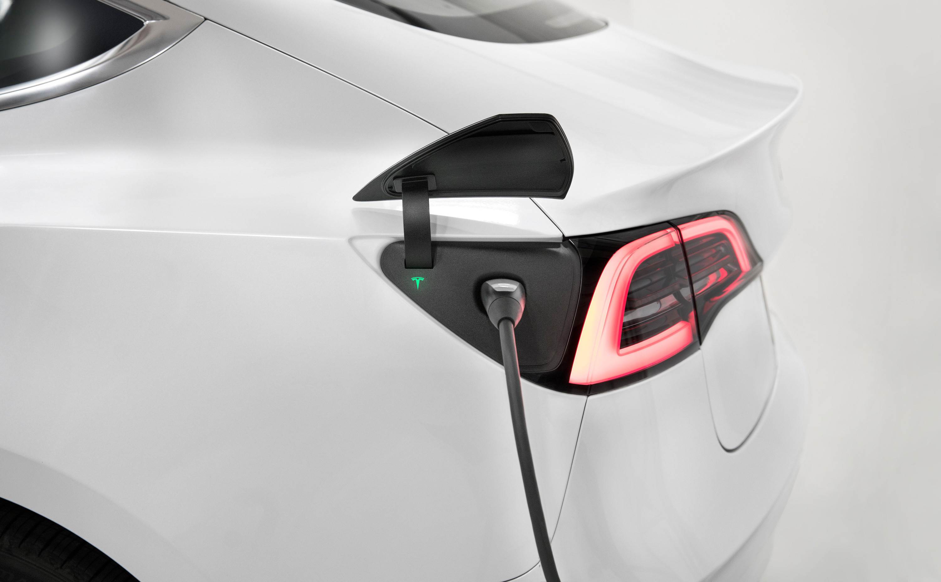
Rear corner
A rear-corner port works well with short cables when the car reverses into a stall. It can conflict with nose-in layouts, curbside charging, rear bicycle carriers, or trailers.
Front side
A front-fender position can serve nose-in or side-access layouts, depending on which side of the car carries the inlet. A port on each front side can improve redundancy or separate AC and DC use, but it adds cost and packaging complexity.
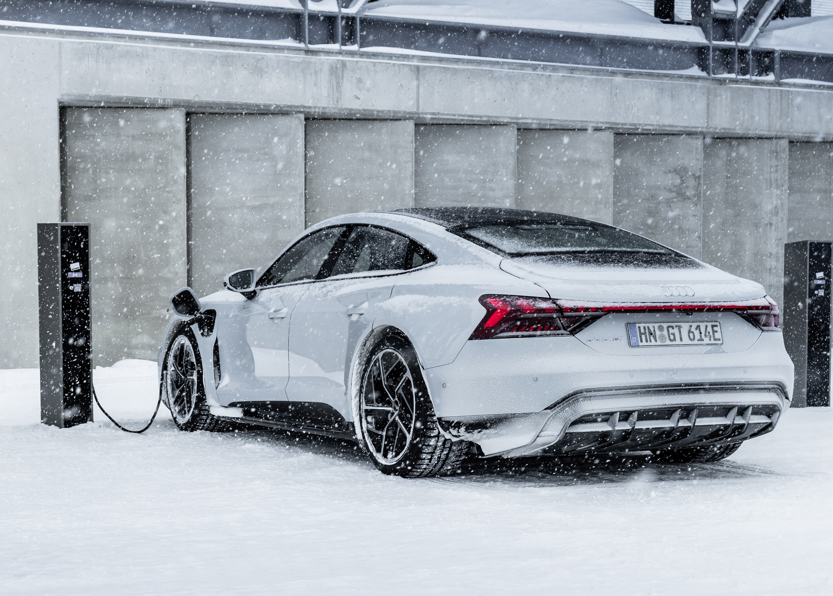
Rear side
A rear-quarter position resembles the fuel-filler location familiar from combustion cars. It works well with many home installations but may require reversing at public sites with short front-mounted cables.

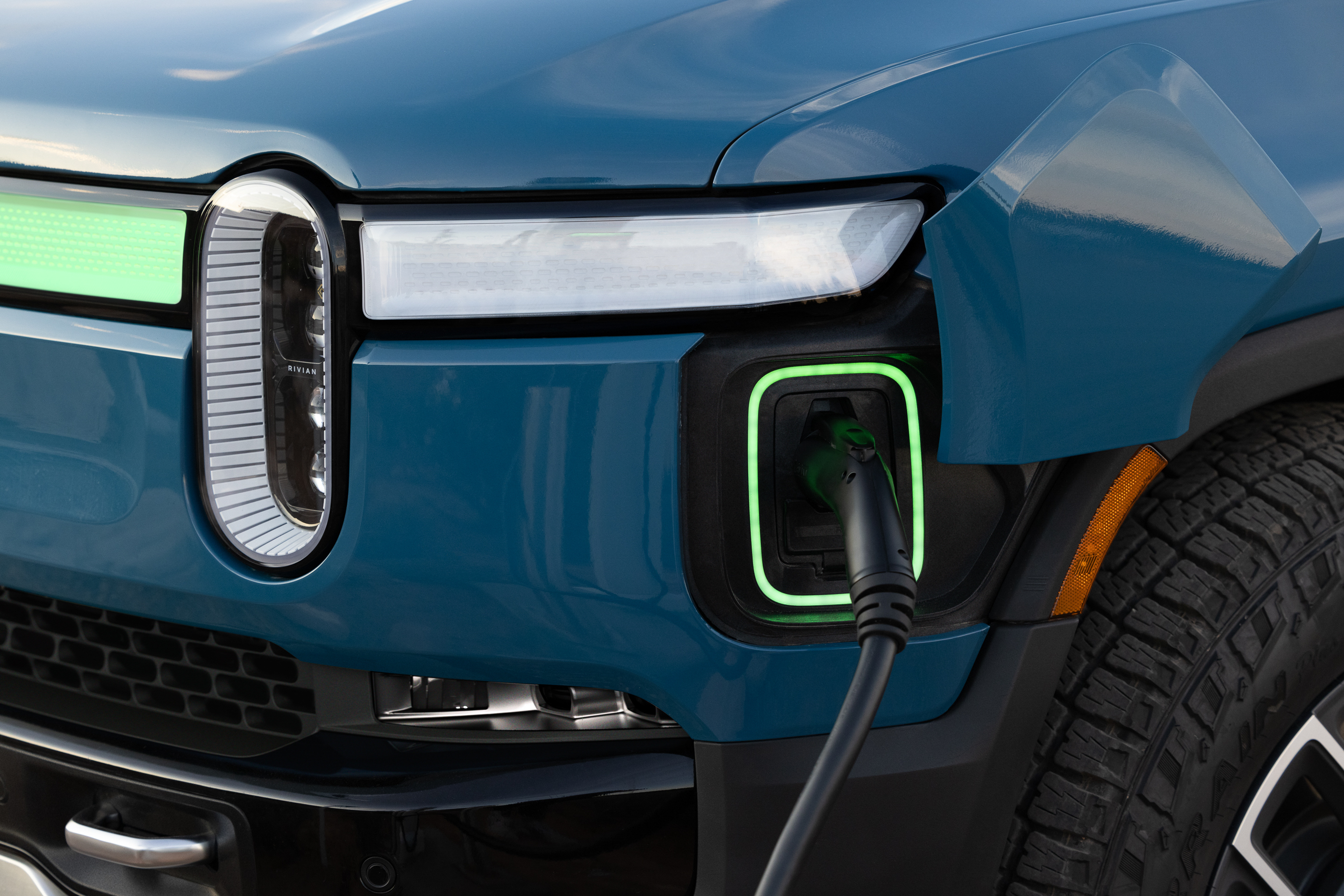
Front corner
A front-corner inlet can be accessible while towing because the trailer remains behind the vehicle. The result still depends on stall geometry; a conventional nose-in space may leave too little room in front of a long vehicle.
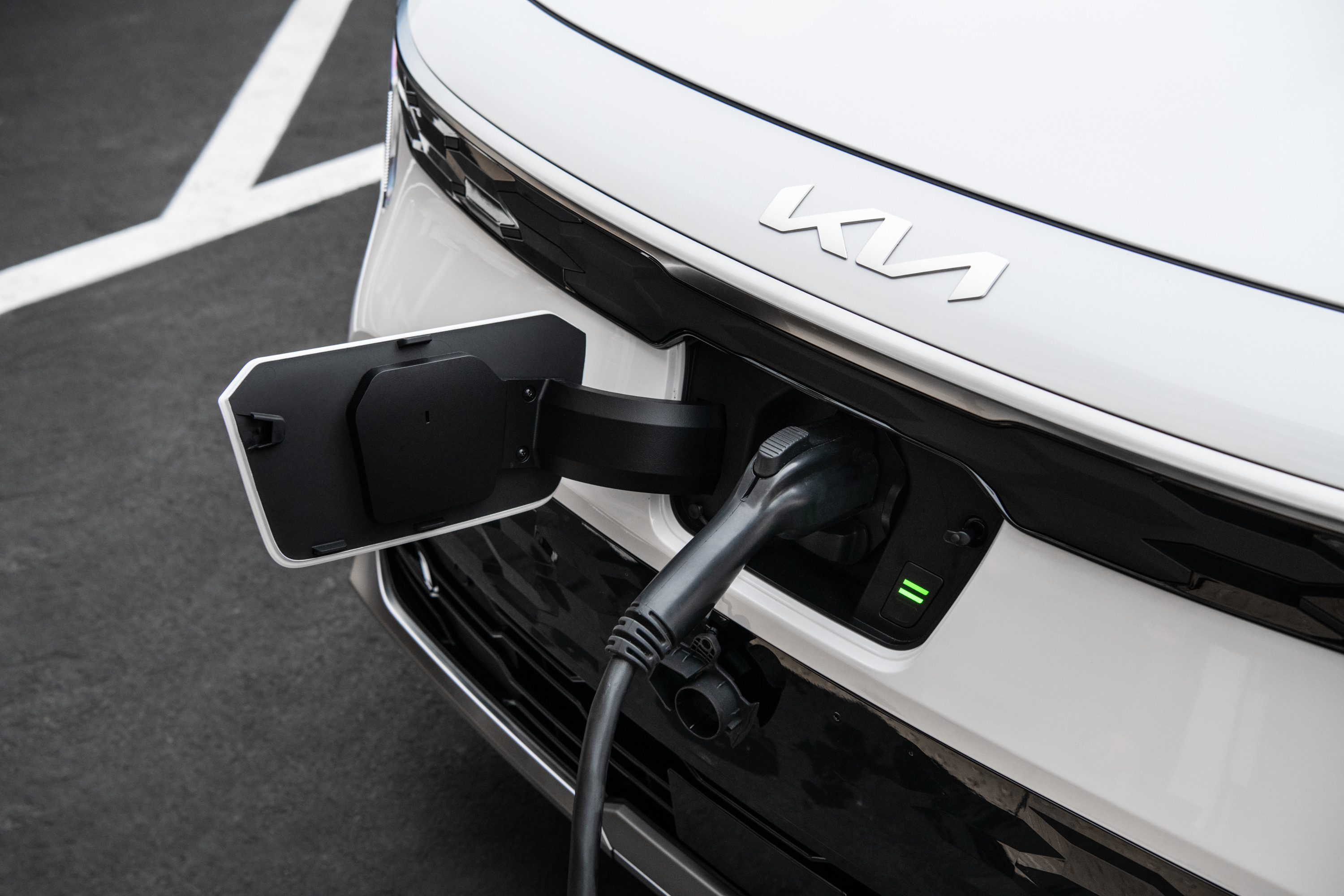
Front centre
A central front inlet is relatively indifferent to left- or right-side traffic and can suit curb-independent nose-in charging. Snow, road salt, minor frontal impacts, and front-mounted accessories place extra demands on sealing and protection.
What drivers should check
Before relying on a station or adapter, verify:
- The exact inlet fitted to the vehicle in that market
- AC versus DC compatibility
- Station voltage and current range, not only headline power
- Cable reach for the vehicle's inlet position
- Whether an adapter is required, approved, and supported by the network
- Whether the vehicle and station software support the same charging and authorization method
- Whether the connector is tethered or the driver must bring a cable
The connector answers “can these surfaces mate?” The complete charging system answers “can they transfer useful power safely?”
Sources
- SAE J1772 — North American conductive charge coupler
- SAE J3400/2 — Connectors and inlets for NACS
- SAE J3400/1 — Charging-adapter safety and OEM-qualified designation
- IEC 62196-2:2025 — AC charging accessories
- EU Delegated Regulation 2025/656 — Charging interoperability standards
- CharIN — Overview of charging connectors used worldwide
- CHAdeMO Association — CHAdeMO 2.1 release
- CHAdeMO Association — ChaoJi high-power charging
- China MIIT — 2023 GB/T conductive-charging connector standards
- GB/T 20234.4-2023 — High-power DC charging coupler