
Sensors and Cameras
Vehicle sensors do not drive the car by themselves. They provide uncertain evidence that software must interpret, combine and validate before an assistance or automated-driving function can act.
The sensor stack
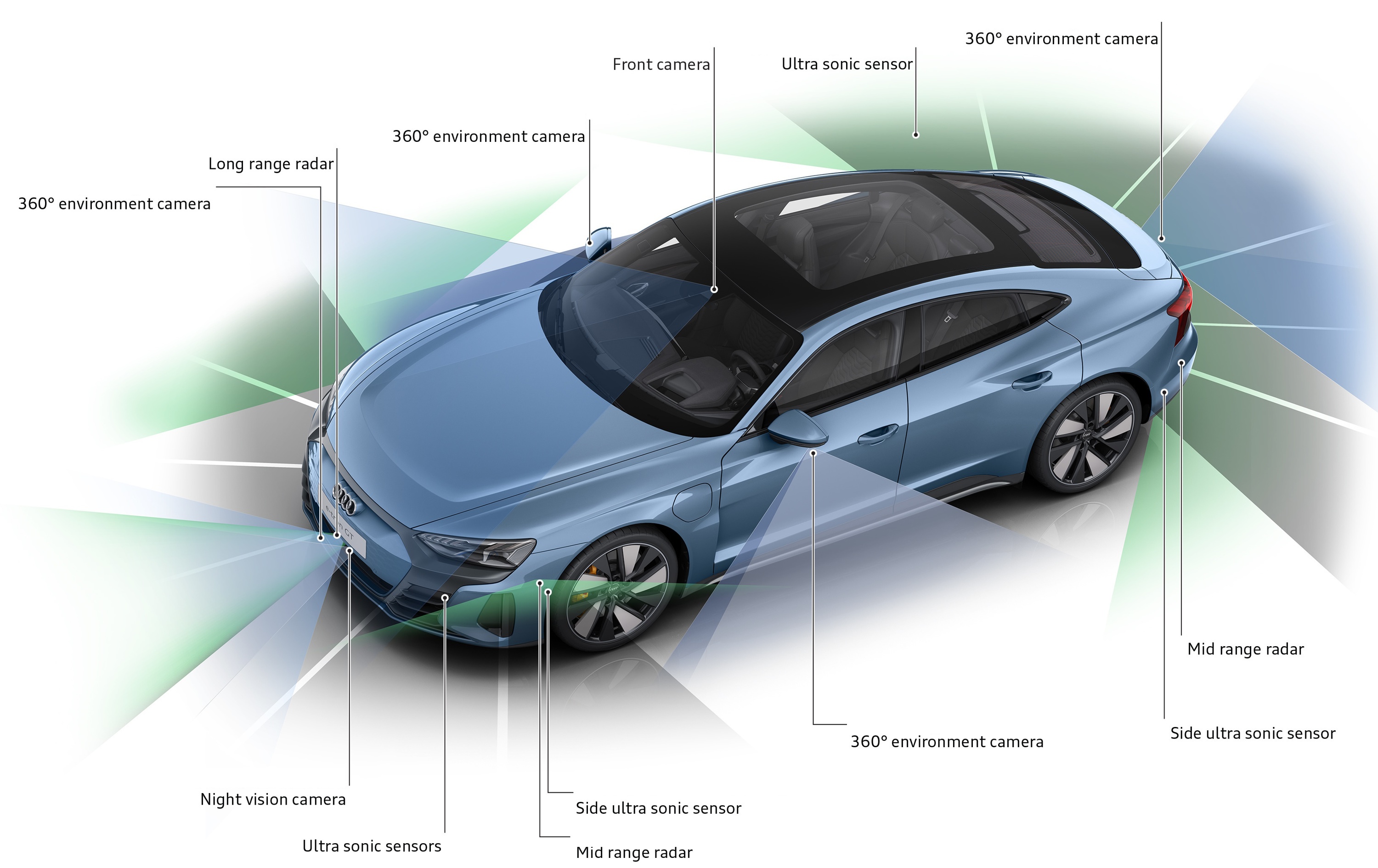
Modern vehicles observe the road through several physical principles:
- Cameras capture visible-light patterns with dense detail, color and texture.
- Radar measures radio reflections, range and radial velocity.
- Lidar samples range with emitted laser light and builds explicit 3D geometry.
- Ultrasonic sensors measures short-range echoes for the area close to the body.
- Infrared and thermal cameras can detect near-infrared illumination or thermal contrast outside normal visible-light imaging.
- Positioning and vehicle motion combines GNSS, inertial sensing, wheel motion, maps and perceived landmarks to estimate the vehicle's own state.
These descriptions concern measurement. Object detection, free-space estimation, prediction, planning and control are software functions built on top of those measurements.
From measurements to driving functions
A driver-assistance feature normally depends on several kinds of evidence:
- Lane departure warning and lane centering need road-boundary or lane-geometry estimates, most often from forward cameras.
- Adaptive cruise control needs a stable target track and relative motion; implementations may use radar, cameras or both.
- Automatic emergency braking needs hazard detection, path relevance, time-to-collision estimation and braking authority. Camera, radar and sometimes lidar can contribute.
- Blind-spot and cross-traffic functions often use corner radar, while cameras or ultrasonic sensors can add context at low speed.
- Parking systems combine near-field cameras, ultrasonic sensors and, on some vehicles, short-range radar.
- Traffic-light and stop-sign response normally depends heavily on cameras because signal state, shape, text and lane association are visual-semantic tasks.
The active sensor set is vehicle-, hardware- and software-specific. A function name does not reveal the architecture, and the presence of a sensor does not prove that every feature uses it. The Driver Assistance Systems series explains what each function does; the next editorial pass will add configuration-aware sensor references consistently.
Advanced Level 2 can look highly automated
A system may follow a navigation route, steer through intersections, change lanes and respond to red lights or stop signs while remaining SAE Level 2. The classification remains Level 2 when the human must continuously supervise the environment and the system and perform fallback.
Sensor capability therefore does not determine the automation level. The relationship between perception, the dynamic driving task and fallback is developed in Sensors in autonomous driving, SAE Level 2 versus Level 3 and operational design domain.
Why systems combine sensors
Different modalities can constrain different uncertainties. A camera can distinguish a red traffic light from a green one; radar can provide direct radial velocity to a vehicle ahead; lidar can provide detailed 3D range; an inertial unit can bridge a temporary positioning gap.
Sensor fusion explains how software aligns these observations in space and time. It also separates complementarity, where sensors provide different useful information, from redundancy, where a defined function can tolerate a relevant failure. More sensors do not automatically create either a better estimate or a safe fallback.
Camera-only and multimodal architectures
Tesla has made camera-centric perception a central engineering and product strategy and Elon Musk has publicly criticized lidar for Tesla's approach. Other developers, including Waymo, Mercedes-Benz and Mobileye, use combinations of camera, radar and lidar.
Camera-only vs multimodal sensing evaluates those choices without using the sensor list as a verdict. A camera-only system is not automatically unsafe; a multimodal system is not automatically safe. The evidence has to match the feature, hardware version, operating conditions and fallback responsibility.
Sensors fail as installed systems
Range and resolution are only part of performance. Placement, field of view, latency, calibration, heating, cleaning, repair and self-diagnosis determine whether the measurement remains usable on the vehicle. See Calibration, cleaning and sensor health.
Weather claims need similar discipline. Radar is comparatively insensitive to ambient light, but not immune to rain clutter, multipath or interference. Lidar works in darkness, but fog, rain, snow and contamination can reduce useful returns. Cameras can extract rich semantics, but glare, low contrast and blocked lenses matter. Thermal contrast also changes with the scene and atmosphere.
How EVKX evaluates sensor claims
EVKX separates:
- the physical measurement;
- the perception algorithm;
- the driving decision;
- the resulting vehicle behavior.
How to validate sensor and perception claims explains why a supplier range number, a single demonstration or a successful feature in one condition cannot prove an architecture. Relevant evidence includes target definition, false alarms, environmental conditions, software version, repeatability, vehicle-level behavior and the claimed operational design domain. ISO 21448 addresses hazards caused by insufficiencies in sensing and algorithms even without a conventional component fault. See ISO 21448:2022 — Safety of the intended functionality.
Reading this series
Start with the sensor modality you want to understand, then use the system chapters:
- Sensor fusion for data association, uncertainty and redundancy;
- Camera-only vs multimodal sensing for camera-only versus multimodal claims;
- Positioning and vehicle motion for GNSS, inertial sensing, maps and localization;
- Calibration, cleaning and sensor health for alignment, contamination, repair and degraded operation;
- How to validate sensor and perception claims for interpreting specifications and safety evidence.
The central rule is simple: evaluate the complete function in its stated operating domain, not the sensor label in isolation.