
Induction (Asynchronous) Motors in EVs
An induction motor—also called an asynchronous motor—creates rotor magnetism without permanent magnets or a separate rotor power supply. Its simple squirrel-cage rotor, controllable field, and high-speed capability make it a durable EV traction option.
How induction creates torque
The inverter feeds the stator’s three phase windings with currents displaced in time. Together, those currents create a magnetic field that rotates around the air gap. The field’s rotational speed is set by electrical frequency and the motor’s number of magnetic poles.
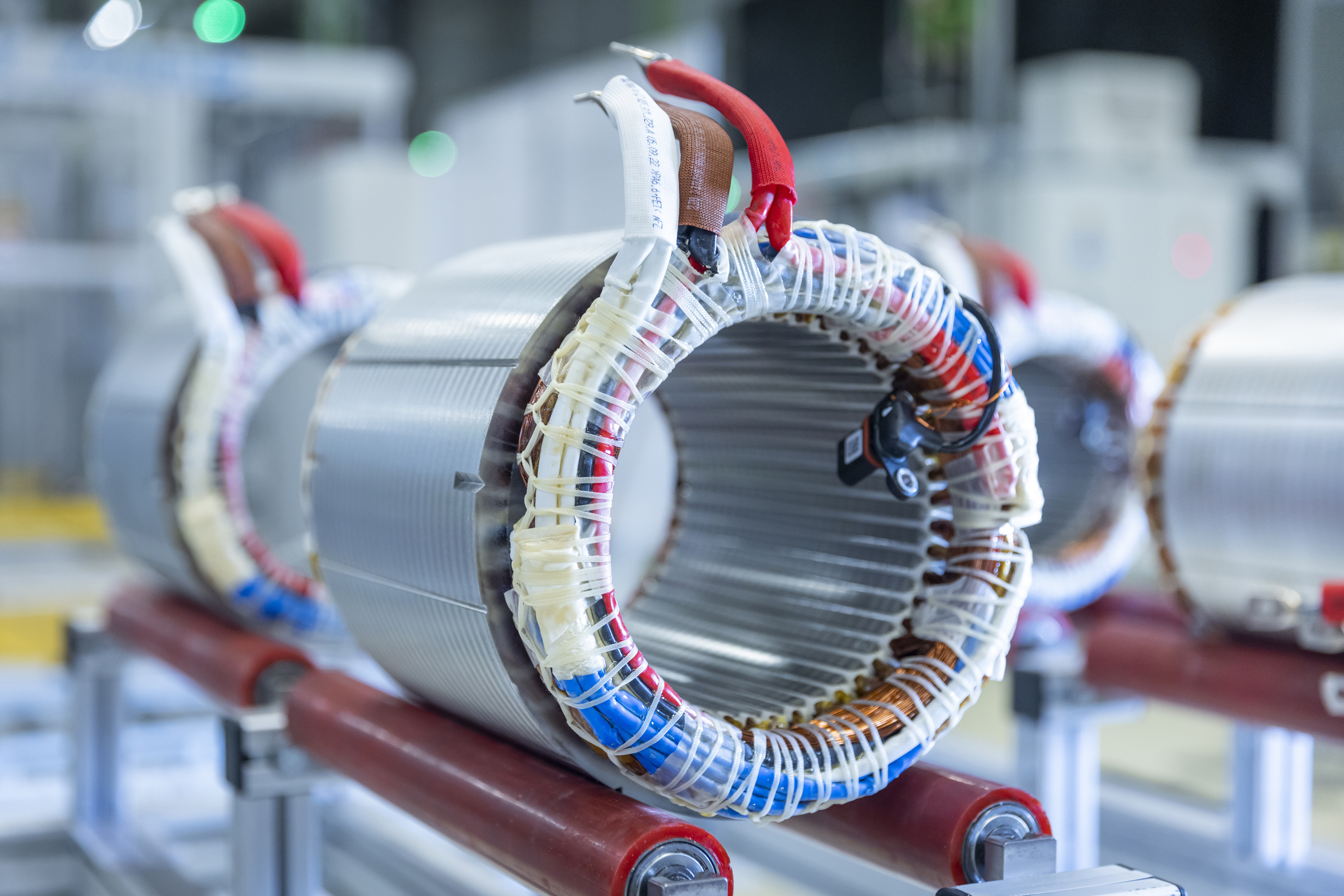
The usual traction-motor rotor is a squirrel cage: conductive aluminium or copper bars run along laminated steel and are shorted together by end rings. The rotating stator field cuts those bars and induces current in them. That current creates a rotor magnetic field, and the interaction between the two fields produces torque.
The rotor must turn at a different speed from the stator field for induction to occur. This difference is called slip. In motoring operation the rotor normally lags the rotating field; in generating operation, including regenerative braking, the controlled relationship reverses so mechanical power becomes electrical power.
Slip is a feature, not a fault
Slip is often expressed as a percentage of synchronous speed. It changes with torque demand and is not the same as wheel slip. At light load, the required electromagnetic slip can be small. Higher torque generally requires more rotor current and a larger controlled speed difference.
The inverter does much more than apply a fixed AC supply. Vector control estimates or measures rotor flux and separates the current commands that establish flux from those that create torque. By continuously changing phase current and frequency, the controller can produce smooth torque from standstill through the field-weakening region.
Three-phase operation creates a smooth rotating field; it does not remove the need for reduction gears. Most induction-motor EV drive units still reduce the motor’s high shaft speed before sending torque to the wheels.
Rotor construction and heat
Passenger-EV induction motors normally use a squirrel-cage rotor because it has no brushes, slip rings, magnets, or insulated rotor windings. Wound-rotor induction machines exist, but they are not the normal architecture for a modern passenger-EV traction unit and should not be confused with an electrically excited synchronous motor.
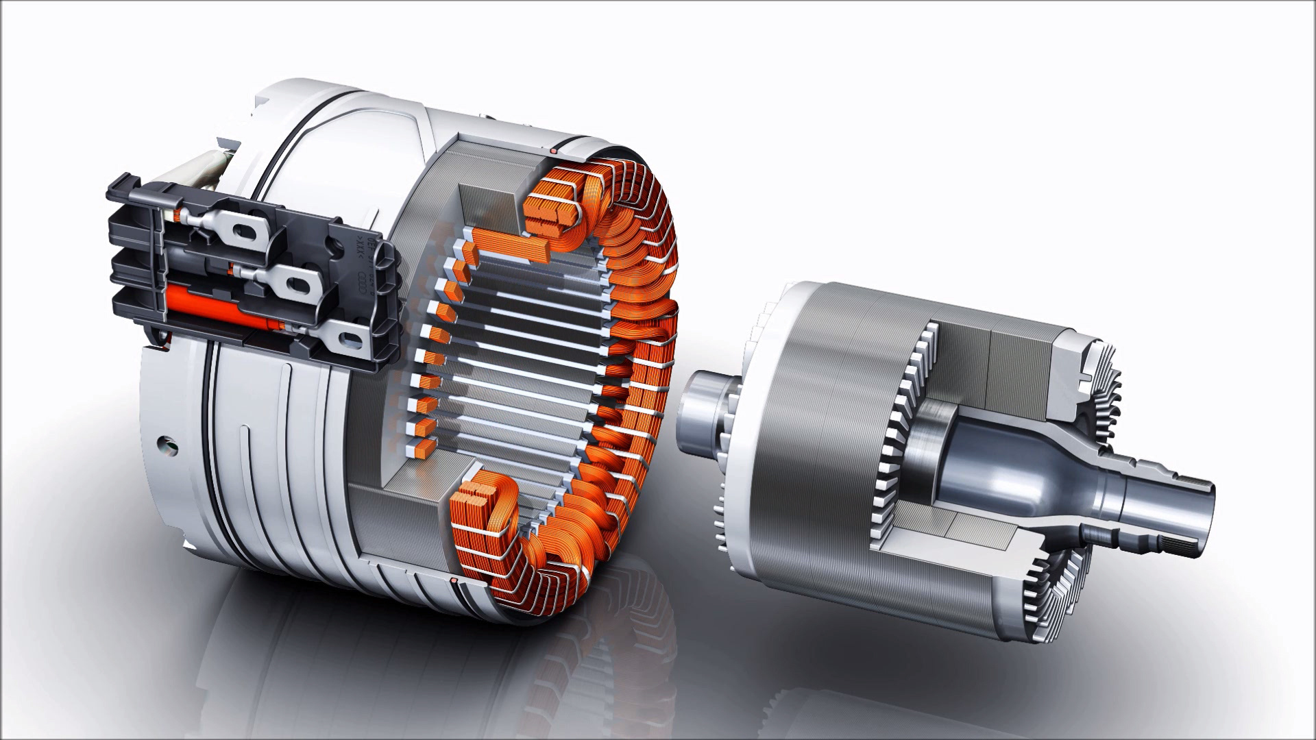
The absence of rotor magnets simplifies material sourcing, but induction does not mean loss-free magnetization. Stator current must establish the air-gap field and transfer power to the rotor. Electrical resistance in the cage turns some of the induced rotor current into heat. At high load, removing that heat from a rotating component can be one of the drive unit’s main thermal challenges.
Strengths in an EV
An induction rotor is mechanically simple and can tolerate high rotational speed when its cage, laminations, shaft, and bearings are designed for the resulting stress. There is no risk of permanent-magnet demagnetization and no rare-earth magnet content in the rotor.
The inverter can reduce the machine’s flux when little torque is needed. When a secondary-axle induction motor is de-energized, it can spin with low electromagnetic drag because it has no permanent rotor field. Bearing, seal, gear, oil-churning, and residual electromagnetic losses remain, so “no drag” should not be read literally.
Induction motors can also accept short overloads when the inverter, battery, and cooling system have enough margin. This is useful for brief acceleration, but temperature—not the word “induction”—sets the repeatable limit.
Limits and design trade-offs
Rotor copper loss and the magnetizing current supplied by the stator can reduce system efficiency and power factor compared with a well-optimized permanent-magnet drive at some operating points. They also increase inverter current for a given shaft output.
Those comparisons are map-dependent. An induction motor is not inherently inefficient at high speed, and a permanent-magnet motor is not automatically superior everywhere. Rotor design, electrical steel, air gap, cooling, switching strategy, gear ratio, and the vehicle duty cycle determine the result.
Accurate control also depends on rotor-temperature and parameter estimation because cage resistance changes as the rotor heats. The controller must maintain stable flux and torque without direct electrical access to the rotor.
How EV makers use induction motors
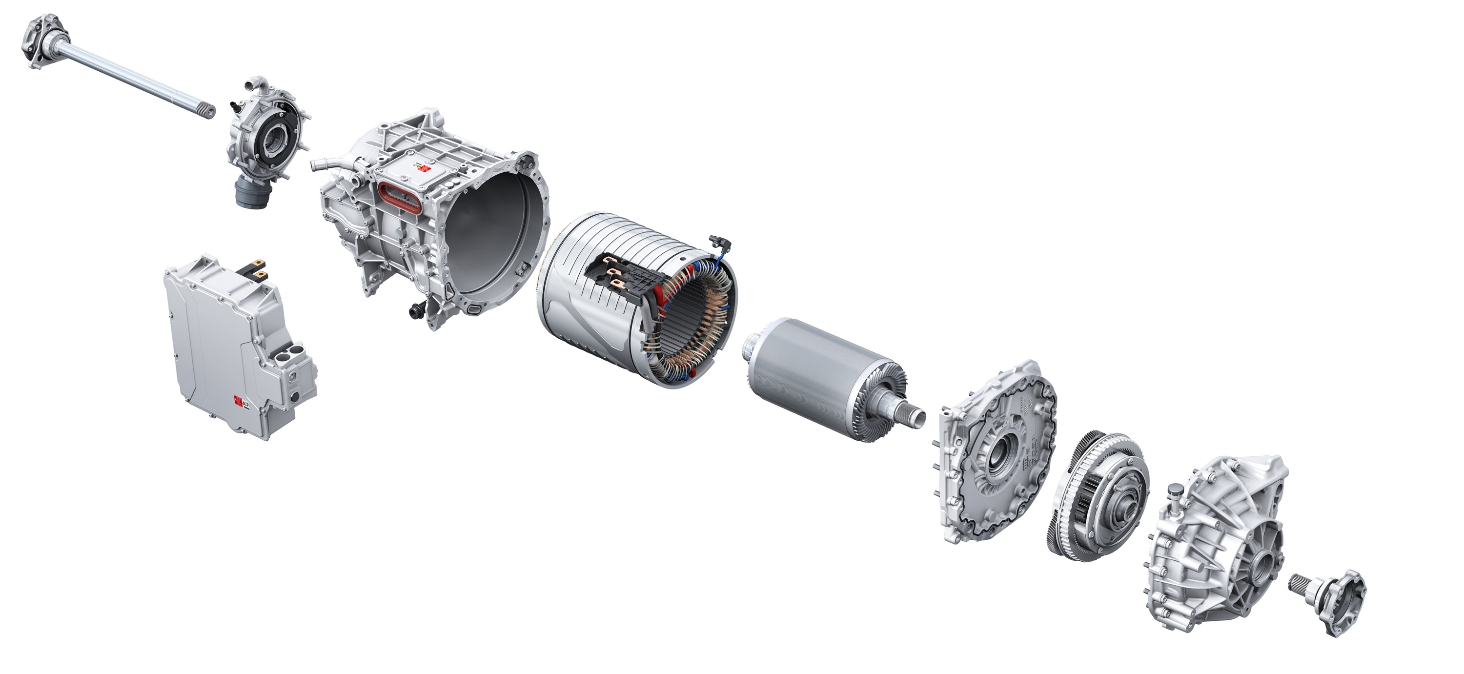
An induction motor can be the main drive motor or a boost motor on a second axle. Audi’s PPE drive system provides a clear mixed-motor example: a permanent-magnet synchronous motor supplies the primary rear-axle drive, while a front induction motor is energized when additional performance or traction is required. When inactive, the front motor can rotate with low drag.
This arrangement is a system choice, not a universal rule. A vehicle’s real efficiency depends on how often each axle operates, whether a clutch is fitted, the gear and tyre losses, and how the control software selects operating points.
Return to Electric Motors and Drive Units.